6REAR PANEL CONNECTIONS AND CONTROLS continued
Correct Speaker Polarity is Important
As you connect the speaker wires, you can see that the insulation on one of the two wires in each pair has either printing or a raised ridge. The marking lets you know which wire you con- nected to the positive speaker terminal at its other end.
Make sure the + wire you attach to each Model 275 + speaker terminal is attached to the + terminal of the speaker for that channel.
Bridging Switch: Stereo - Mono
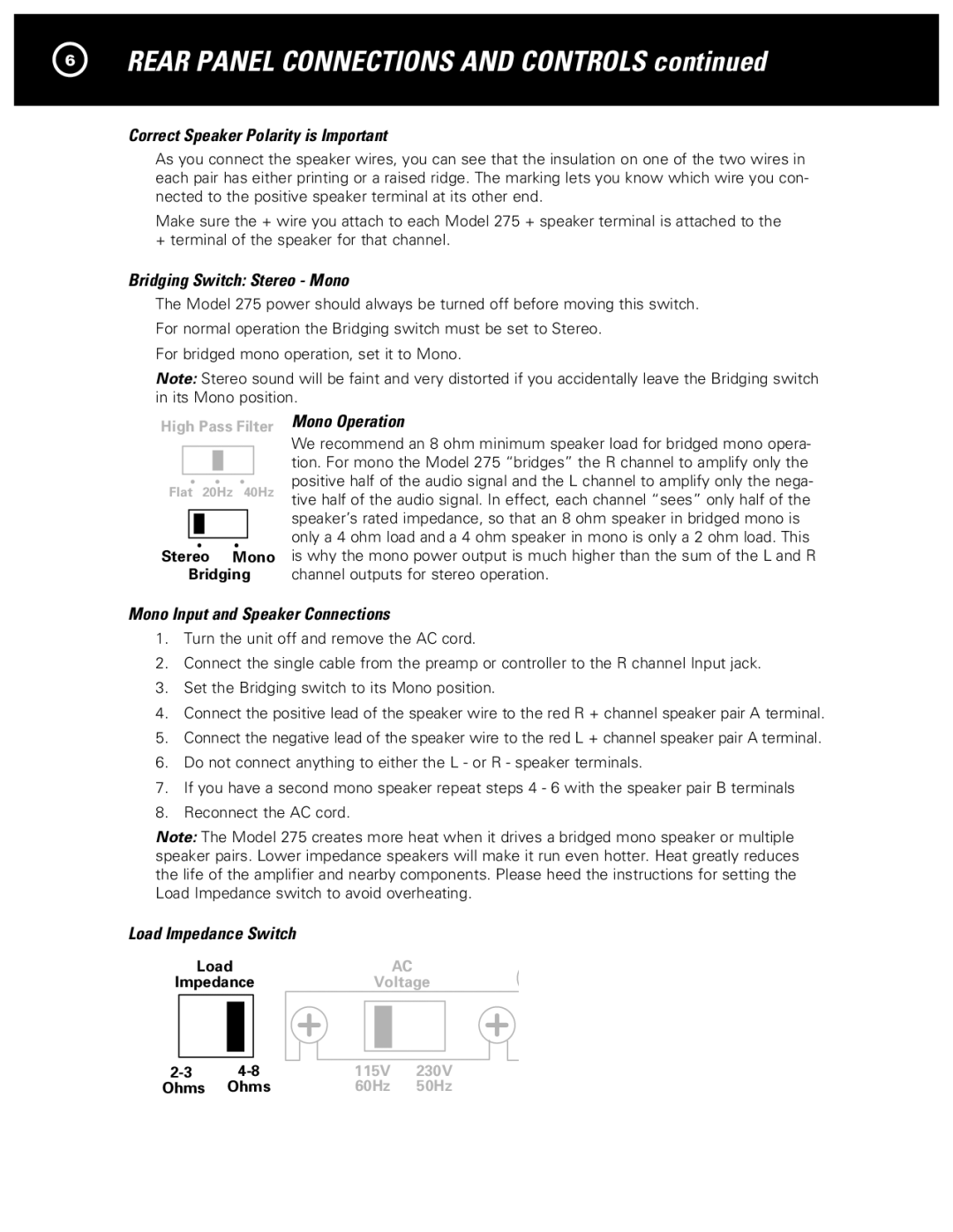
The Model 275 power should always be turned off before moving this switch. For normal operation the Bridging switch must be set to Stereo.
For bridged mono operation, set it to Mono.
Note: Stereo sound will be faint and very distorted if you accidentally leave the Bridging switch in its Mono position.
High Pass Filter
Flat 20Hz 40Hz
Stereo Mono
Bridging
Mono Operation
We recommend an 8 ohm minimum speaker load for bridged mono opera- tion. For mono the Model 275 “bridges” the R channel to amplify only the positive half of the audio signal and the L channel to amplify only the nega- tive half of the audio signal. In effect, each channel “sees” only half of the speaker’s rated impedance, so that an 8 ohm speaker in bridged mono is only a 4 ohm load and a 4 ohm speaker in mono is only a 2 ohm load. This is why the mono power output is much higher than the sum of the L and R channel outputs for stereo operation.
Mono Input and Speaker Connections
1.Turn the unit off and remove the AC cord.
2.Connect the single cable from the preamp or controller to the R channel Input jack.
3.Set the Bridging switch to its Mono position.
4.Connect the positive lead of the speaker wire to the red R + channel speaker pair A terminal.
5.Connect the negative lead of the speaker wire to the red L + channel speaker pair A terminal.
6.Do not connect anything to either the L - or R - speaker terminals.
7.If you have a second mono speaker repeat steps 4 - 6 with the speaker pair B terminals
8.Reconnect the AC cord.
Note: The Model 275 creates more heat when it drives a bridged mono speaker or multiple speaker pairs. Lower impedance speakers will make it run even hotter. Heat greatly reduces the life of the amplifier and nearby components. Please heed the instructions for setting the Load Impedance switch to avoid overheating.
Load Impedance Switch
LoadAC
ImpedanceVoltage
115V 230V 60Hz 50Hz
