REAR PANEL CONNECTIONS AND CONTROLS continued | 5 |
High Pass Filter Switch
The High Pass filter can improve the sound in virtually any installation. It’s called a “high pass” filter because it permits signals higher than 20 Hz and 40 Hz to pass, while preventing signals below these frequencies from passing.
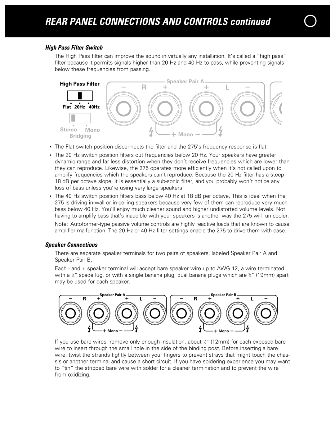
High Pass Filter
Flat 20Hz 40Hz
Speaker Pair A
R ![]()
![]() L
L
Stereo Mono | Mono |
|
Bridging | CA | |
| WARNING: To Prevent Fire Or Shock Hazard, |
•The Flat switch position disconnects the filter and the 275’s frequency response is flat.
•The 20 Hz switch position filters out frequencies below 20 Hz. Your speakers have greater dynamic range and far less distortion when they don’t receive frequencies which are lower than they can reproduce. Likewise, the 275 operates more efficiently when it’s not called upon to amplify frequencies which the speakers can’t reproduce. Because the 20 Hz filter has a steep 18 dB per octave slope, it is essentially a
•The 40 Hz switch position filters bass below 40 Hz at 18 dB per octave. This is ideal when the 275 is driving
Note:
Speaker Connections
There are separate speaker terminals for two pairs of speakers, labeled Speaker Pair A and Speaker Pair B.
Each - and + speaker terminal will accept bare speaker wire up to AWG 12, a wire terminated with a 1⁄4” spade lug, or with a single banana plug; dual banana plugs which are 3⁄4” (19mm) apart may be used for each speaker.
R | Speaker Pair A | R | Speaker Pair B |
L | L |
Mono | Mono |
If you use bare wires, remove only enough insulation, about 1⁄2” (12mm) for each exposed bare wire to insert through the small hole in the side of the binding post. Before inserting a bare wire, twist the strands tightly between your fingers to prevent strays that might touch the chas- sis or another terminal and cause a short circuit. If you have soldering experience you may want to “tin” the stripped bare wire with solder for a cleaner termination and to prevent the wire from oxidizing.