CONNECTING YOUR SPEAKERS TO THE A 51 | 5 |
|
|
Speaker Terminals
The A 51 speaker terminals accept speaker wires with banana plugs or bare ends. Refer to Bare Wire Speaker Termination in the Technically Speaking section for information about bare wire termination.
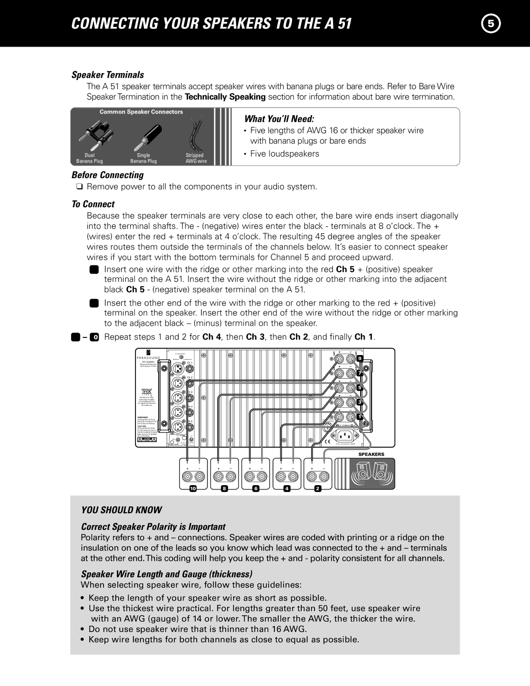
Common Speaker Connectors
Dual | Single | Stripped |
Banana Plug | Banana Plug | AWG wire |
What You’ll Need:
•Five lengths of AWG 16 or thicker speaker wire with banana plugs or bare ends
•Five loudspeakers
Before Connecting
❑Remove power to all the components in your audio system.
To Connect
Because the speaker terminals are very close to each other, the bare wire ends insert diagonally into the terminal shafts. The - (negative) wires enter the black - terminals at 8 o’clock. The + (wires) enter the red + terminals at 4 o’clock. The resulting 45 degree angles of the speaker wires routes them outside the terminals of the channels below. It’s easier to connect speaker wires if you start with the bottom terminals for Channel 5 and proceed upward.
1Insert one wire with the ridge or other marking into the red Ch 5 + (positive) speaker terminal on the A 51. Insert the wire without the ridge or other marking into the adjacent black Ch 5 - (negative) speaker terminal on the A 51.
2Insert the other end of the wire with the ridge or other marking to the red + (positive) terminal on the speaker. Insert the other end of the wire without the ridge or other marking to the adjacent black – (minus) terminal on the speaker.
3 – 0 Repeat steps 1 and 2 for Ch 4, then Ch 3, then Ch 2, and finally Ch 1.
A51 Amplifier
Parasound Products, Inc. San Francisco, CA USA
L U C A S F I L M
Manufactured under license from Lucasfilm Ltd. Lucasfilm and THX are registered Trademarks of Lucasfilm Ltd.
WARNING
To Prevent Fire Or Shock
Hazard, Do Not Expose This
Unit To Rain Or Moisture.
CAUTION
To Prevent Electric Shock,
Do Not Remove Cover. No
Refer Servicing To Qualified
Service Personnel.
| Input Select |
|
|
| |
Balanced | Unbalanced |
|
| ||
|
| Ch 1 |
|
| |
|
| Ch 2 |
|
| |
|
| Ch 3 |
|
| |
|
| Ch 4 |
|
| |
|
|
|
| Fuse |
|
|
| Ch 5 |
| ||
|
|
| |||
|
|
|
| AC 115V | 60Hz |
|
|
|
| AC 230V | 50Hz |
| Audio |
| Lift |
|
|
Man |
|
|
|
| |
| 12 V | 50 mV 250 | Normal | Power Consumption: 1800W | |
Input |
| Sensitivity | Ground | ||
| Auto Turn On |
|
| ||
9
7
5
3
1
SPEAKERS
10 | 8 | 6 | 4 | 2 |
YOU SHOULD KNOW
Correct Speaker Polarity is Important
Polarity refers to + and – connections. Speaker wires are coded with printing or a ridge on the insulation on one of the leads so you know which lead was connected to the + and – terminals at the other end.This coding will help you keep the + and - polarity consistent for all channels.
Speaker Wire Length and Gauge (thickness)
When selecting speaker wire, follow these guidelines:
•Keep the length of your speaker wire as short as possible.
•Use the thickest wire practical. For lengths greater than 50 feet, use speaker wire with an AWG (gauge) of 14 or lower. The smaller the AWG, the thicker the wire.
•Do not use speaker wire that is thinner than 16 AWG.
•Keep wire lengths for both channels as close to equal as possible.