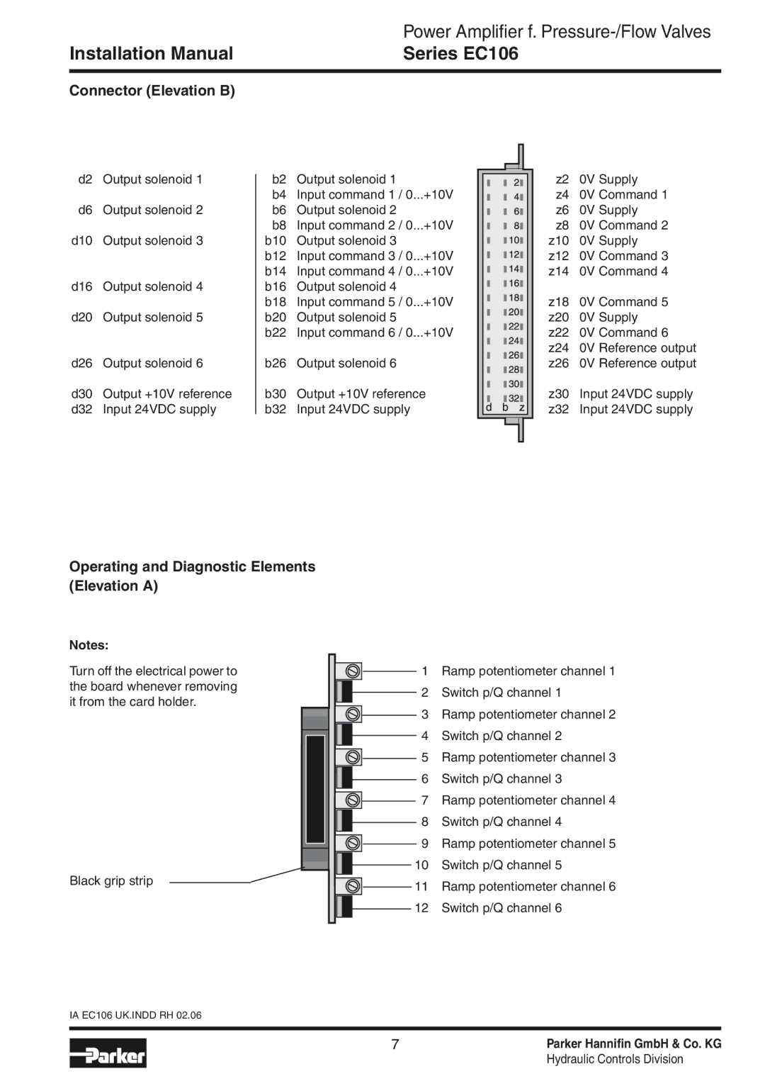
EC106 specifications
Parker Hannifin EC106 is a leading-edge product from Parker Hannifin Corporation, a global leader in motion and control technology. The EC106 is designed to address the growing needs of various industries, including aerospace, automotive, and industrial automation. This advanced electronic control unit provides enhanced performance and reliability, making it an ideal solution for modern applications.One of the main features of the EC106 is its compact and lightweight design. Measuring just a few inches, it easily integrates into tight spaces, making it suitable for a range of equipment and machinery. The construction ensures durability and resistance to vibration, which is critical for the demanding environments in which it operates.
The EC106 employs state-of-the-art technology, including advanced algorithms and high-precision sensors, to deliver optimal control and performance. This electronic control unit is equipped with real-time diagnostics and monitoring capabilities, allowing users to quickly identify potential issues and take corrective actions. With built-in safety features, the EC106 ensures operational reliability, enhancing the overall safety of the application it serves.
Another key characteristic of the EC106 is its versatility. The unit is compatible with various control architectures and can be easily integrated into existing systems. It supports multiple communication protocols, including CAN bus and Ethernet, allowing for seamless connectivity with other devices and systems. This flexibility enables manufacturers to adopt the EC106 without the need for significant redesign or overhaul of their existing infrastructure.
Additionally, the EC106 offers programmable features that enable customization and adaptability. Users can tailor the control settings to meet specific requirements, optimizing performance based on their unique applications. This adaptability is particularly valuable in industries where requirements may rapidly change or evolve, allowing companies to stay competitive in a dynamic market landscape.
In summary, the Parker Hannifin EC106 electronic control unit provides exceptional features such as compactness, advanced technology, versatility, and programmability. Its robust performance and reliability make it a standout option for industries that require precise control and efficient operation in challenging conditions. With its ability to integrate seamlessly into existing systems, the EC106 is an investment that promises long-term value for users across various sectors.

