4.0 INSTALLATION
Once you have properly configured the DTE/DCE switch, you are ready to connect the Model 1000 to your system. This section tells you how to properly connect the Model 1000 to the twisted pair and
4.1 CONNECTION TO THE TWISTED PAIR INTERFACE
The Model 1000 supports
19.2 Kbps. There are two essential requirements for installation:
1.These units work in pairs. Therefore, you must have one Model 1000 at each end of a two twisted pair interface.
2.To function properly, the Model 1000 needs two twisted pair of metallic wire. The pairs must be unconditioned, dry metallic wire, between 19 and 26 AWG (.4mm to .9mm) (the higher number gauges may limit distance). Standard
For your convenience, the Model 1000 is available with three different twisted pair interfaces:
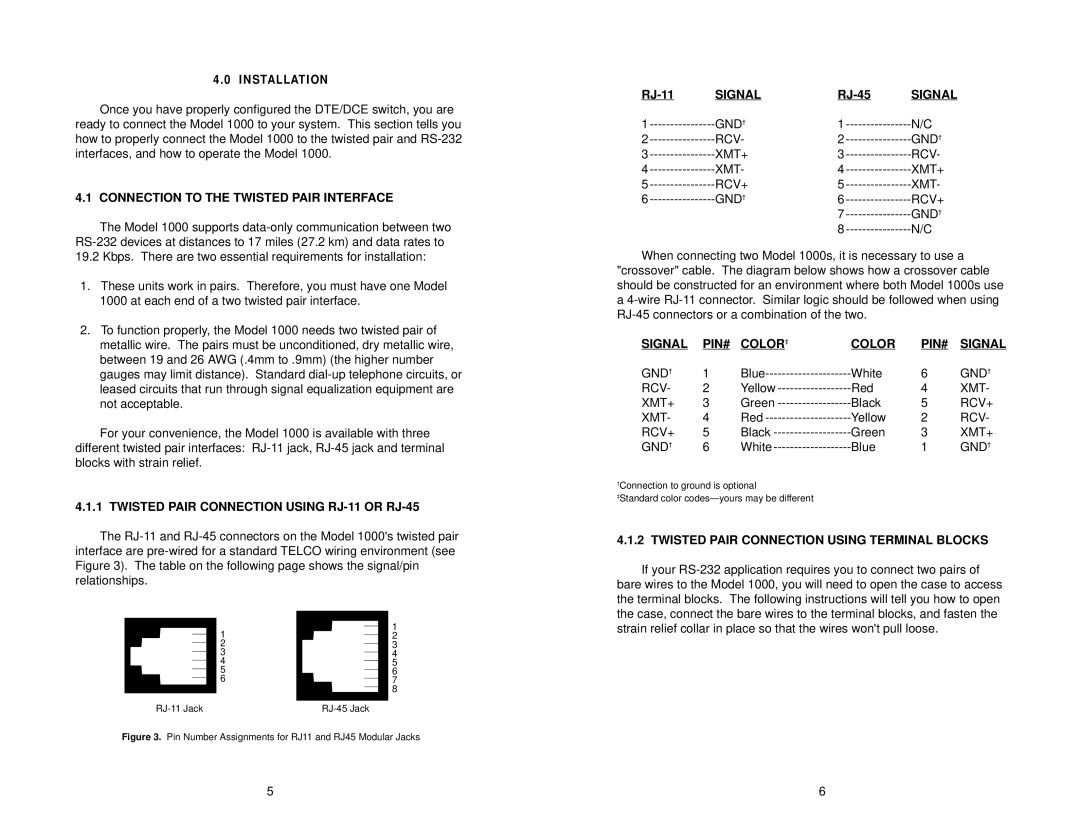
4.1.1 TWISTED PAIR CONNECTION USING RJ-11 OR RJ-45
The
SIGNAL | SIGNAL | ||
1 | GND† | 1 | N/C |
2 | RCV- | 2 | GND† |
3 | XMT+ | 3 | RCV- |
4 | XMT- | 4 | XMT+ |
5 | RCV+ | 5 | XMT- |
6 | GND† | 6 | RCV+ |
|
| 7 | GND† |
|
| 8 | N/C |
When connecting two Model 1000s, it is necessary to use a
"crossover" cable. The diagram below shows how a crossover cable should be constructed for an environment where both Model 1000s use a
SIGNAL | PIN# | COLOR‡ | COLOR | PIN# | SIGNAL |
GND† | 1 | White | 6 | GND† | |
RCV- | 2 | Yellow | Red | 4 | XMT- |
XMT+ | 3 | Green | Black | 5 | RCV+ |
XMT- | 4 | Red | Yellow | 2 | RCV- |
RCV+ | 5 | Black | Green | 3 | XMT+ |
GND† | 6 | White | Blue | 1 | GND† |
†Connection to ground is optional
‡Standard color
4.1.2 TWISTED PAIR CONNECTION USING TERMINAL BLOCKS
If your
1
2
3
4
5
6
1
2
3
4
5
6
7
8
strain relief collar in place so that the wires won't pull loose.
Figure 3. Pin Number Assignments for RJ11 and RJ45 Modular Jacks
5 | 6 |