JB2
Position 1&2 = Line A Shield Connected to Frame Ground Position 2&3 = No Shield
JB4
Position 1&2 = Line B Shield Connected to Frame Ground Position 2&3 = No Shield
SGND & FRGND (JB5)
In position 1&2, this strap links signal ground and frame ground through a 100 Ohm, 1/2 W resistor. In position 2&3, pin 1 is “not connected to frame ground.
JB5
Position 1&2 = SGND and FRGND Connected
Position 2&3 = SGND and FRGND Not Connected
DTE as DSR or RI (JB6 & JB7)
Because the Model 1000RC uses DSR (but not RI), only position 1&2 is valid when this rear card is used with the Model 1000RC. Position 1&2 causes the terminal (DTE) to see DSR when the Model 1000RC is powered up properly. Position 2&3 is for Ring Indicate, which is
JB6 & JB7
Position 1&2 = DSR
Position 2&3 = (Ring Indicate) Not Valid for Model 1000RC
4.0 INSTALLATION
This section describes the functions of the Model 1000R16P rack chassis, tells how to install front and rear Model 1000RC cards into the chassis and provides diagrams for wiring up the interface connections correctly.
4.1 THE MODEL 1000R16P RACK CHASSIS
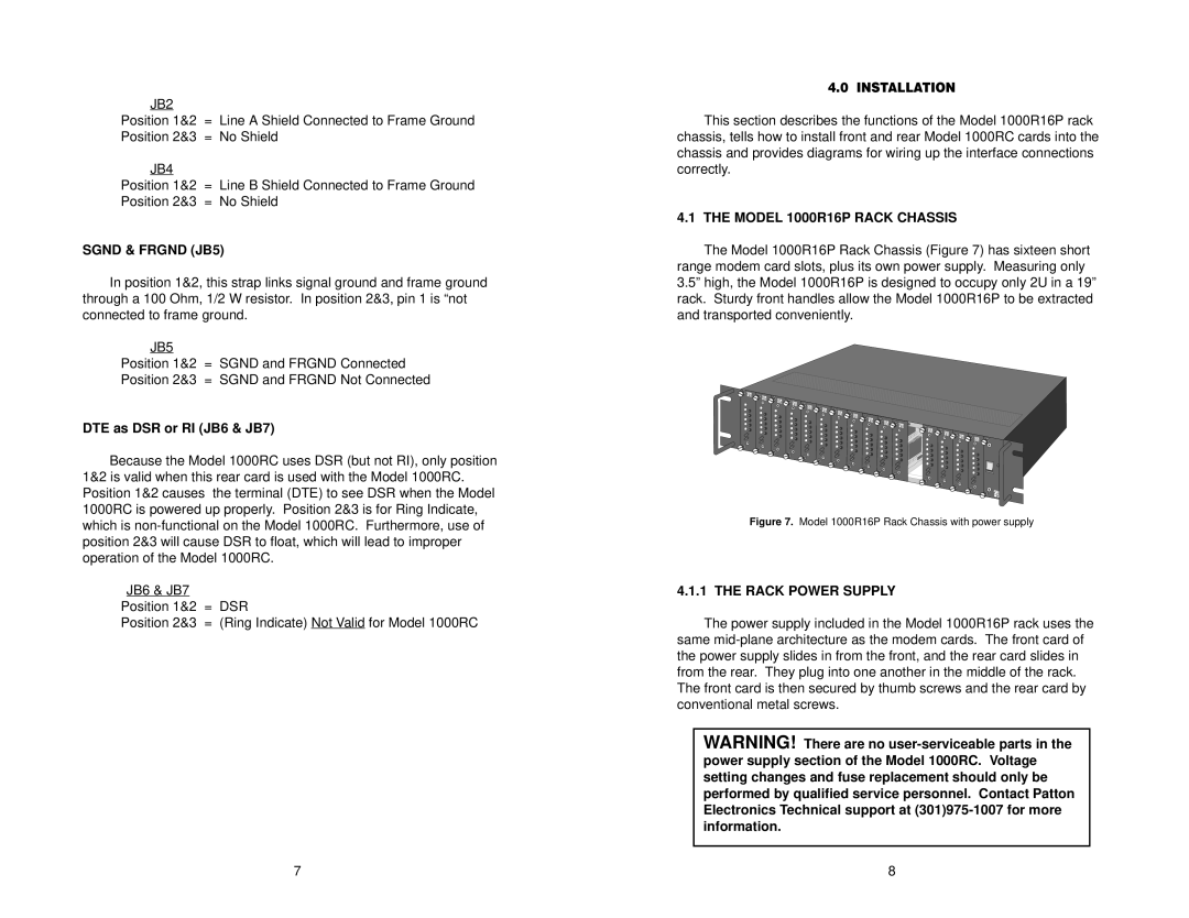
The Model 1000R16P Rack Chassis (Figure 7) has sixteen short range modem card slots, plus its own power supply. Measuring only 3.5” high, the Model 1000R16P is designed to occupy only 2U in a 19” rack. Sturdy front handles allow the Model 1000R16P to be extracted and transported conveniently.
Figure 7. Model 1000R16P Rack Chassis with power supply
4.1.1 THE RACK POWER SUPPLY
The power supply included in the Model 1000R16P rack uses the same
WARNING! There are no
7 | 8 |