Switching the Power Supply On and Off
The power switch is located on the front panel. When plugged in and switched on, a red front panel LED will glow. Since the Model 1000R16P is a “hot swappable” rack,it is not necessary for any cards to be installed before switching on the power supply. The power supply may be switched off at any time without harming the installed cards.
4.2 INSTALLING THE MODEL 1000RC INTO THE CHASSIS
The Model 1000RC is comprised of a front card and a rear card. The two cards meet inside the rack chassis and plug into each other by way of mating 50 pin card edge connectors. Use the following steps as a guideline for installing each Model 1000RC into the Model 1000R16P rack chassis:
1.Slide the rear card into the back of the chassis along the metal rails.
2.Secure the rear card using the metal screws provided.
3.Slide the front card into the front of the chassis. It should meet the rear card when it's almost all the way into the chassis.
4.Push the front card gently into the
5.Secure the front card using the thumb screws.
Note: Since the Model 1000R16P chassis allows “hot swapping” of cards, it is not necessary to power down the rack when you install or remove a Model 1000RC.
4.3 RS-232 CONNECTION
The
Notice! Any terminal cable connected to the Model 1000RC must be shielded cable, and the outer shield must be 360 degree
(continued)
9
The Model 1000RC is wired as a DCE (Data Communications Equipment). Therefore, it wants to connect to a DTE (Data Termination Equipment). If your
4.4 TWISTED PAIR CONNECTION
The Model 1000RC operates full duplex over two twisted pair. In all applications, the twisted pair wire must be 26 AWG or thicker, unconditioned, dry, metallic wire. Both shielded and unshielded wire are satisfactory. Note: The Model 1000RC can only be installed on private twisted pair cable.
Notice! Any modular twisted pair cable connected to the Model 1000RC must be shielded cable, and the outer shield must be properly terminated to a shielded modular plug on both ends of the cable.
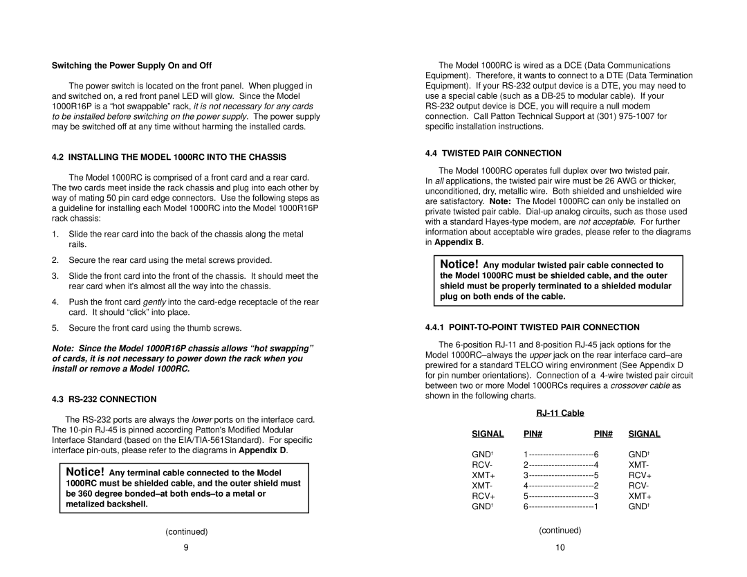
4.4.1 POINT-TO-POINT TWISTED PAIR CONNECTION
The
|
|
| |
SIGNAL | PIN# | PIN# | SIGNAL |
GND† | 6 | GND† | |
RCV- | 4 | XMT- | |
XMT+ | 5 | RCV+ | |
XMT- | 2 | RCV- | |
RCV+ | 3 | XMT+ | |
GND† | 1 | GND† |
(continued)
10