S1-3: Reserved
Switch
Setting | |
On | Not a Valid Setting |
Off | Default Setting |
S1-4: Echo Mode
The setting for switch
Setting | |
On | Echo On |
Off | Echo Off |
SWITCH SET “S2”
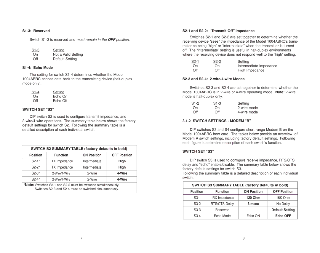
DIP switch S2 is used to configure transmit impedance, and
SWITCH S2 SUMMARY TABLE (factory defaults in bold)
Position | Function | ON Position | OFF Position |
|
|
|
|
TX Impedance | Intermediate | High | |
|
|
|
|
TX Impedance | Intermediate | High | |
|
|
|
|
|
|
|
|
|
|
|
|
*Note: Switches
S2-1 and S2-2: “Transmit Off” Impedance
Switches
Setting | ||
On | On | Intermediate Impedance |
Off | Off | High Impedance |
S2-3 and S2-4: 2-wire/4-wire Modes
Switches
Setting | ||
On | On | |
Off | Off |
3.1.2 SWITCH SETTINGS - MODEM “B”
DIP switches S3 and S4 configure short range Modem B on the Model 1004ABRC front card. The tables below provide an overview of Modem A switch settings, including factory default settings. Following each figure is a detailed description of each switch’s function.
SWITCH SET “S3”
DIP switch S3 is used to configure receive impedance, RTS/CTS delay and “echo” enable/disable. The summary table below shows the factory default settings for switch S3.
Following the summary table is a detailed description of each individual switch.
SWITCH S3 SUMMARY TABLE (factory defaults in bold)
Position | Function | ON Position | OFF Position |
|
|
|
|
RX Impedance | 120 Ohm | 16K Ohm | |
|
|
|
|
RTS/CTS Delay | 8 msec | No Delay | |
|
|
|
|
Reserved | - | Default Setting | |
|
|
|
|
Echo Mode | Echo ON | Echo OFF | |
|
|
|
|
7 | 8 |
