3.0 CONFIGURATION
This section describes the location and orientation of the Model 1004ABRC's configuration switches, provides detailed instructions on setting each switch and describes the settings for each of the rear con- nection cards.
3.1 FRONT CARD CONFIGURATION
The Model 1004ABRC front card houses two short
S2 ![]()
S1![]()
![]()
![]()
![]()
![]()
![]()
S4 ![]()
S3
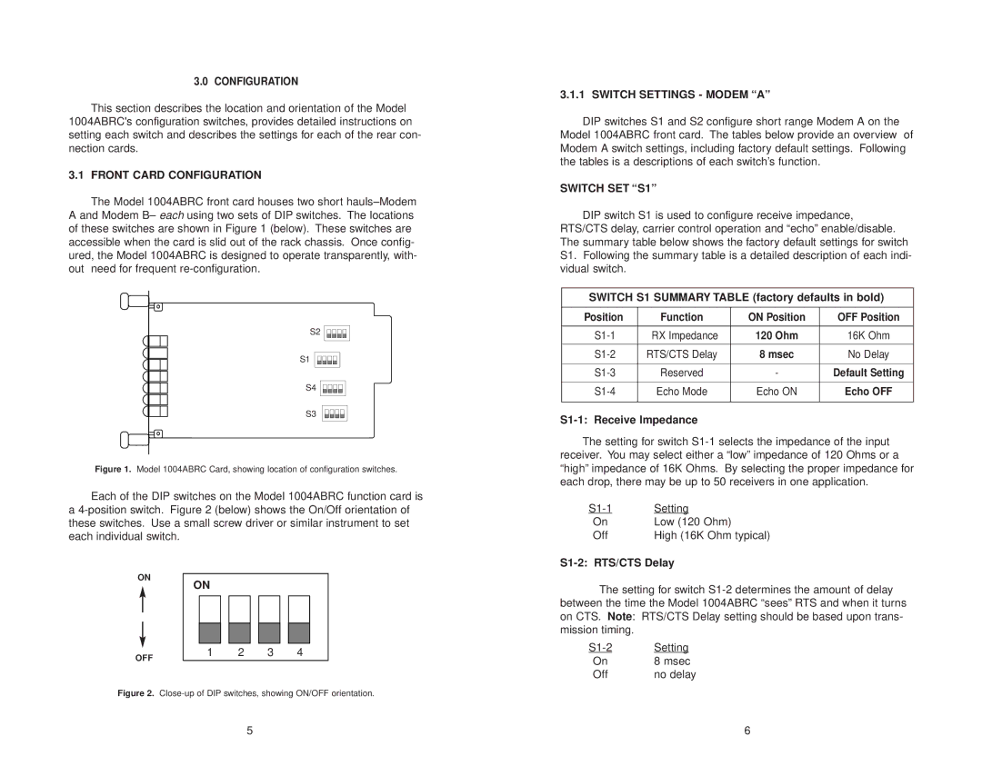
Figure 1. Model 1004ABRC Card, showing location of configuration switches.
Each of the DIP switches on the Model 1004ABRC function card is a
ON
ON
OFF | 1 | 2 | 3 | 4 |
|
|
|
|
Figure 2. Close-up of DIP switches, showing ON/OFF orientation.
3.1.1 SWITCH SETTINGS - MODEM “A”
DIP switches S1 and S2 configure short range Modem A on the Model 1004ABRC front card. The tables below provide an overview of Modem A switch settings, including factory default settings. Following the tables is a descriptions of each switch’s function.
SWITCH SET “S1”
DIP switch S1 is used to configure receive impedance, RTS/CTS delay, carrier control operation and “echo” enable/disable. The summary table below shows the factory default settings for switch S1. Following the summary table is a detailed description of each indi- vidual switch.
SWITCH S1 SUMMARY TABLE (factory defaults in bold)
Position | Function | ON Position | OFF Position |
|
|
|
|
RX Impedance | 120 Ohm | 16K Ohm | |
|
|
|
|
RTS/CTS Delay | 8 msec | No Delay | |
|
|
|
|
Reserved | - | Default Setting | |
|
|
|
|
Echo Mode | Echo ON | Echo OFF | |
|
|
|
|
S1-1: Receive Impedance
The setting for switch
Setting | |
On | Low (120 Ohm) |
Off | High (16K Ohm typical) |
S1-2: RTS/CTS Delay
The setting for switch
Setting | |
On | 8 msec |
Off | no delay |
5 | 6 |