4.0 INSTALLATION
Once you have properly configured the DTE/DCE switch, you are ready to connect the Model 1010A to your system. This section tells you how to properly connect the Model 1010A to the twisted pair and
4.1 CONNECTION TO THE TWISTED PAIR INTERFACE
The Model 1010A supports
1)These units work in pairs. Therefore, you must have one Model
1010A at each end of a two twisted pair interface.
2)To function properly, the Model 1010A needs two twisted pairs of metallic wire. These pairs must be unconditioned, dry metallic wire, between 19 and 26 AWG (the higher number gauges may limit distance somewhat). Standard
For your convenience, the Model 1010A is available with three different twisted pair interfaces:
4.1.1 TWISTED PAIR CONNECTION USING RJ-11 OR RJ-45
The
SIGNAL | SIGNAL | ||
1 | GND* | 1 | N/C |
2 | RCV- | 2 | GND* |
3 | XMT+ | 3 | RCV- |
4 | XMT- | 4 | XMT+ |
5 | RCV+ | 5 | XMT- |
6 | GND | 6 | RCV+ |
|
| 7 | GND |
|
| 8 | N/C |
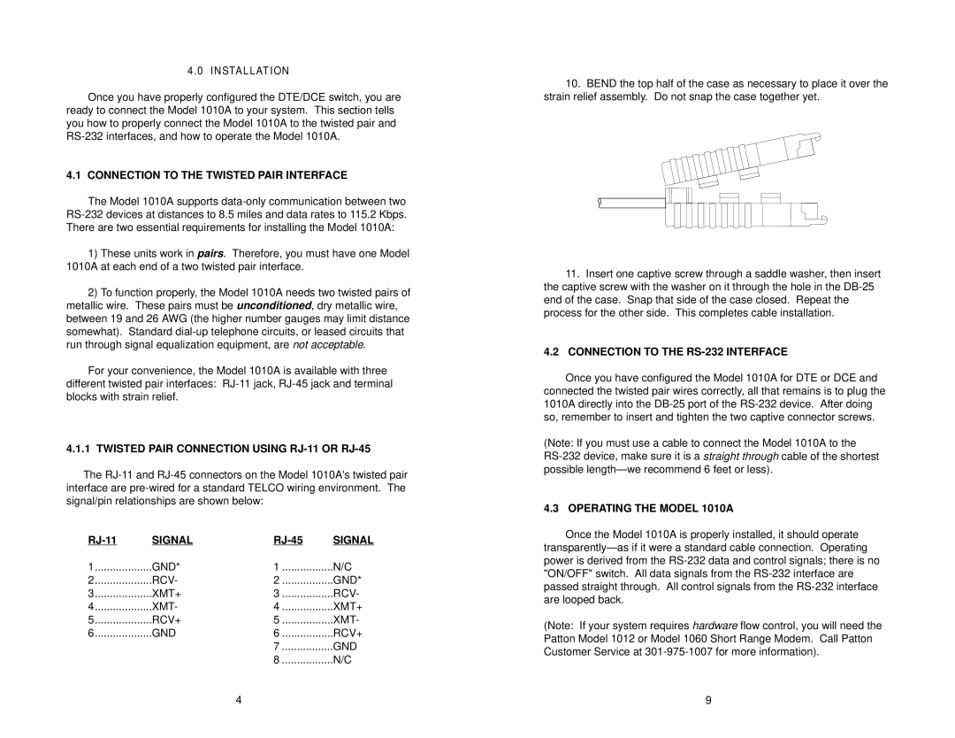
10.BEND the top half of the case as necessary to place it over the strain relief assembly. Do not snap the case together yet.
11.Insert one captive screw through a saddle washer, then insert the captive screw with the washer on it through the hole in the
4.2CONNECTION TO THE RS-232 INTERFACE
Once you have configured the Model 1010A for DTE or DCE and connected the twisted pair wires correctly, all that remains is to plug the 1010A directly into the
(Note: If you must use a cable to connect the Model 1010A to the
4.3 OPERATING THE MODEL 1010A
Once the Model 1010A is properly installed, it should operate
(Note: If your system requires hardware flow control, you will need the Patton Model 1012 or Model 1060 Short Range Modem. Call Patton Customer Service at
4 | 9 |