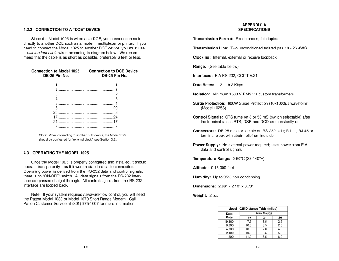
4.2.2 CONNECTION TO A “DCE” DEVICE
Since the Model 1025 is wired as a DCE, you cannot connect it directly to another DCE such as a modem, multiplexer or printer. If you need to connect the Model 1025 to another DCE device, you must use a null modem cable wired according to diagram below. We recom- mend that the cable is as short as possible, preferably 6 feet or less.
Connection to Model 1025† | Connection to DCE Device |
1 | 1 |
2 | 3 |
3 | 2 |
4 | 8 |
8 | 4 |
6 | 20 |
20 | 6 |
17 | 24 |
24 | 17 |
7 | 7 |
†Note: When connecting to another DCE device, the Model 1025 should be configured for “external clock” (see Section 3.2).
4.3OPERATING THE MODEL 1025
Once the Model 1025 is properly configured and installed, it should operate
Note: If your system requires hardware flow control, you will need the Patton Model 1030 or Model 1070 Short Range Modem. Call Patton Customer Service at (301)
APPENDIX A
SPECIFICATIONS
Transmission Format: Synchronous, full duplex
Transmission Line: Two unconditioned twisted pair 19 - 26 AWG
Clocking: Internal, external or receive loopback
Range: (See table below)
Interfaces: EIA
Data Rates: 1.2 - 19.2 Kbps
Isolation: Minimum 1500 V RMS via custom transformers
Surge Protection: 600W Surge Protection (10x1000µs waveform) (Model 1025S)
Control Signals: CTS turns on 8 or 53 mS (switch selectable) after the terminal raises RTS; DSR and DCD are constantly on
Connectors:
Power Supply: No external power required; uses power from EIA data and control signals
Temperature Range: 0-60°C (32-140°F)
Altitude:
Humidity: Up to 95%
Dimensions: 2.66” x 2.10” x 0.73”
Weight: 2 oz.
Model 1025 Distance Table (miles)
Data |
| Wire Gauge |
| |
Rate | 19 |
| 24 | 26 |
19,200 | 7.5 |
| 3.5 | 2.5 |
9,600 | 10.0 |
| 3.5 | 2.5 |
4,800 | 10.0 |
| 7.0 | 4.0 |
2,400 | 10.0 |
| 8.5 | 5.0 |
1,200 | 11.0 |
| 8.5 | 6.0 |
13 | 14 |
