Switch S1-8: V.54 Enable / Disable
The setting for switch
Setting | |
On | Disabled |
Off | Enabled |
3.1.2 Switch Set S2
The settings for DIP switches
Setting | ||||
Off | On | On | On | 384 kbps |
On | Off | Off | Off | 768 kbps (default) |
4.0 INSTALLATION
Once the Model 1094 is properly configured, it is ready to connect to the twisted pair interface, to the serial port, and to the power source. This section tells you how to make these connections.
4.1 CONNECTION TO THE TWISTED PAIR INTERFACE
The Model 1094 supports communication between two terminal devices at distances to 4.9 miles (7.9 km) and data rates to 768 kbps. There are two essential requirements for installing the Model 1094:
1.These units work in pairs. Therefore, you must have one Model 1094 (or a compatible model) at each end of a two twisted pair interface.
2.To function properly, the Model 1094 needs two twisted pairs of metallic wire. These twisted pairs must be unconditioned, dry, metallic wire, between 19 and 26 AWG (.4 mm and .9 mm, inversely) (the higher AWG gauges may limit distance somewhat). Standard
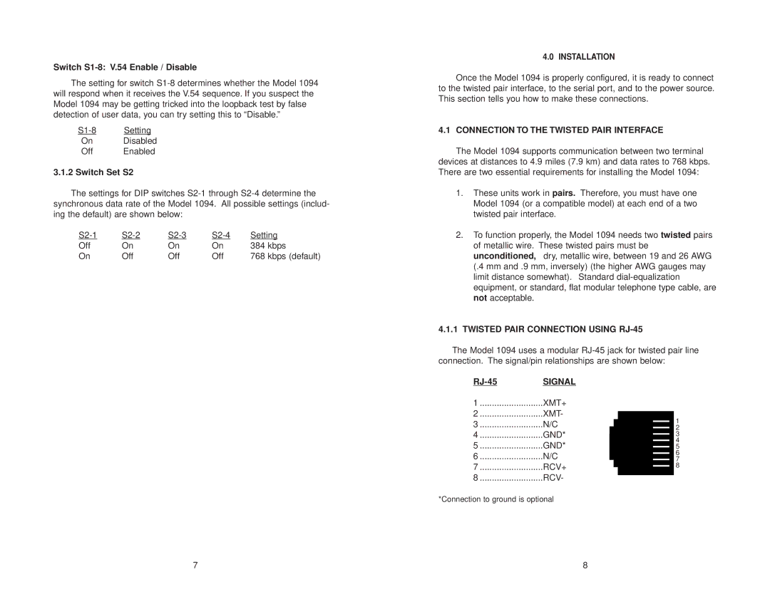
4.1.1TWISTED PAIR CONNECTION USING RJ-45
The Model 1094 uses a modular
SIGNAL |
| |
1 | XMT+ |
|
2 | XMT- |
|
|
| 1 |
3 | N/C | 2 |
4 | GND* | 3 |
|
| 4 |
5 | GND* | 5 |
|
| 6 |
6 | N/C | 7 |
7 | RCV+ | 8 |
8 | RCV- |
|
*Connection to ground is optional |
| |
7 | 8 |