4.0 INSTALLATION
This section describes the functions of the Model 1000R16 rack chassis, tells how to install front and rear Model 1110ARC cards into the chassis, and provides instructions for connecting the interface cables.
4.1 THE MODEL 1000R16 RACK CHASSIS
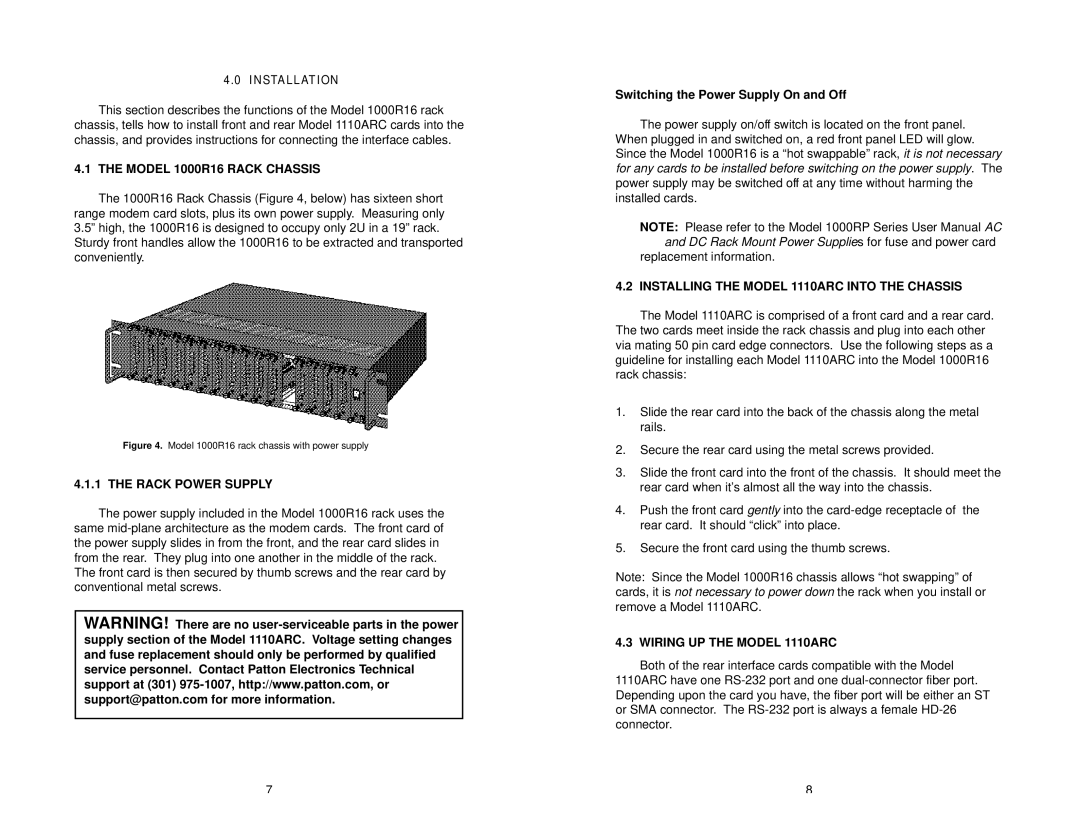
The 1000R16 Rack Chassis (Figure 4, below) has sixteen short range modem card slots, plus its own power supply. Measuring only 3.5” high, the 1000R16 is designed to occupy only 2U in a 19” rack.
Sturdy front handles allow the 1000R16 to be extracted and transported conveniently.
Figure 4. Model 1000R16 rack chassis with power supply
4.1.1 THE RACK POWER SUPPLY
The power supply included in the Model 1000R16 rack uses the same
The front card is then secured by thumb screws and the rear card by conventional metal screws.
WARNING! There are no
Switching the Power Supply On and Off
The power supply on/off switch is located on the front panel. When plugged in and switched on, a red front panel LED will glow. Since the Model 1000R16 is a “hot swappable” rack,it is not necessary for any cards to be installed before switching on the power supply. The power supply may be switched off at any time without harming the installed cards.
NOTE: Please refer to the Model 1000RP Series User Manual AC and DC Rack Mount Power Supplies for fuse and power card
replacement information.
4.2 INSTALLING THE MODEL 1110ARC INTO THE CHASSIS
The Model 1110ARC is comprised of a front card and a rear card. The two cards meet inside the rack chassis and plug into each other via mating 50 pin card edge connectors. Use the following steps as a guideline for installing each Model 1110ARC into the Model 1000R16 rack chassis:
1.Slide the rear card into the back of the chassis along the metal rails.
2.Secure the rear card using the metal screws provided.
3.Slide the front card into the front of the chassis. It should meet the rear card when it’s almost all the way into the chassis.
4.Push the front card gently into the
5.Secure the front card using the thumb screws.
Note: Since the Model 1000R16 chassis allows “hot swapping” of cards, it is not necessary to power down the rack when you install or remove a Model 1110ARC.
4.3 WIRING UP THE MODEL 1110ARC
Both of the rear interface cards compatible with the Model
1110ARC have one
7 | 8 |