3.2 REAR CARD SETTINGS
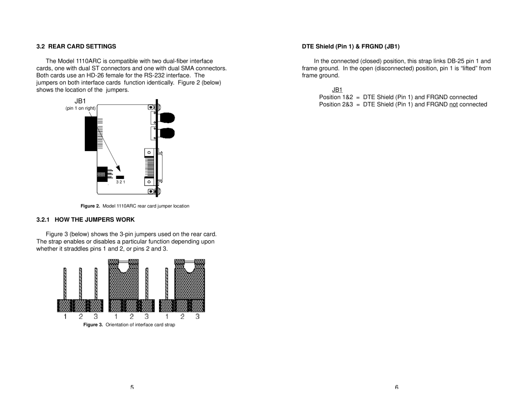
The Model 1110ARC is compatible with two
JB1
(pin 1 on right)
3 2 1
Figure 2. Model 1110ARC rear card jumper location
3.2.1 HOW THE JUMPERS WORK
Figure 3 (below) shows the 3-pin jumpers used on the rear card. The strap enables or disables a particular function depending upon whether it straddles pins 1 and 2, or pins 2 and 3.
Figure 3. Orientation of interface card strap
DTE Shield (Pin 1) & FRGND (JB1)
In the connected (closed) position, this strap links
JB1
Position 1&2 = DTE Shield (Pin 1) and FRGND connected Position 2&3 = DTE Shield (Pin 1) and FRGND not connected
5 | 6 |
