2.0 GENERAL INFORMATION
Thank you for your purchase of this Patton Electronics product. This product has been thoroughly inspected and tested and is warranted for One Year parts and labor. If any questions or problems arise during installation or use of this product, please do not hesitate to contact Patton Electronics Technical Support at (301)
support@patton.com or www.patton.com.
2.1FEATURES
•Supports async or sync communication over dual optical fibers
•
•Distances to 4 miles
•V.54 and V.52 Diagnostics
•Mounts in Patton’s
•Compatible with the Patton Model 1140A
•Immune to RFI/EMI noise, ground loops and transient surges
•Easily accessible configuration jumpers & switches
•
•Works with switchable 120V or 240V rack mount power supply
•SMA or ST connectors available
2.2DESCRIPTION
The Patton Model 1140ARC fiber optic rack card modem is the rack mountable counterpart to Patton’s Model 1140A
The Model 1140ARC is designed to mount in Patton’s 2U high 19” rack chassis. This
3
3.0 CONFIGURATION
This section describes the location and orientation of the Model 1140ARC’s configuration switches and jumpers, and provides detailed instructions for all possible settings.
The Model 1140ARC uses a combination of DIP switches and jumpers that allow configuration to an extremely wide range of applications. Designed around a
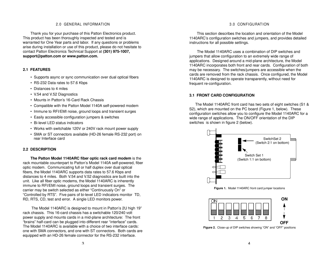
3.1 FRONT CARD CONFIGURATION
The Model 1140ARC front card has two sets of eight switches (S1 & S2), which are mounted on the PC board (Figure 1, below). These configuration switches allow you to configure the Model 1140ARC for a wide range of applications. The ON/OFF orientation of the DIP switches is shown in figure 2 (below).
SwitchSet 2
(Switch 2:1 on bottom)
Switch Set 1
(Switch 1:1 on bottom)
Figure 1. Model 1140ARC front card jumper locations
ON
OFF
Figure 2. Close-up of DIP switches showing “ON” and “OFF” positions
4