1184, 1185 specifications
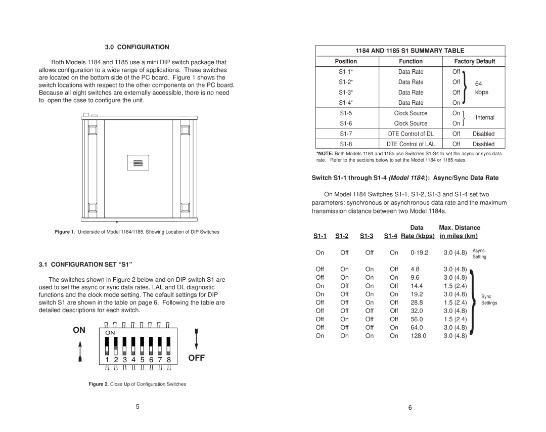
The Patton Electronics 1185 and 1184 models are part of a trusted series of network devices designed to facilitate communication and enhance network performance in various applications. These products are widely recognized for their robust features, user-friendly interface, and reliable performance.The Patton 1185 is primarily a multi-port serial device server that enables the connection of multiple serial devices to an Ethernet network. This model can support up to eight serial ports, offering a straightforward solution for integrating legacy serial devices like POS terminals, industrial equipment, and IoT devices into modern network infrastructures. The 1185 is equipped with standard RS-232, RS-422, or RS-485 interfaces, allowing flexibility in terms of device compatibility. Its ability to convert serial data to TCP/IP makes it ideal for remote monitoring and management applications.
On the other hand, the Patton 1184 serves as a single-port serial device server. Like its counterpart, it provides the functionality to connect serial devices to Ethernet networks. The 1184’s compact design and ease of installation make it suitable for small-scale installations where space is a premium. It supports a variety of serial interfaces, including RS-232, enhancing compatibility with various devices.
Both models feature patented Auto-Sense technology, which automatically adjusts serial port settings to match connected devices, easing the configuration process and reducing setup time. They are equipped with a web-based management interface that allows for simplified configuration, monitoring, and troubleshooting through any web browser.
In terms of reliability, the Patton 1185 and 1184 boast a wide operating temperature range, making them suitable for use in harsh environmental conditions. They also feature surge protection and failover capabilities to ensure consistent data transmission and minimal downtime. Moreover, both models incorporate support for standard networking protocols, including TCP/IP, UDP, and DHCP, facilitating seamless integration into existing networks.
With a commitment to quality and performance, Patton Electronics has designed these models to meet the demands of various sectors, including retail, telecommunications, and industrial automation. The Patton 1185 and 1184 represent innovative solutions that combine functionality, ease of use, and robust construction, making them a preferred choice for businesses looking to modernize their communications infrastructure.

