Loop Timeout

The Loop Timeout setting can be set to one of the following:

00:05 =

five minutes

00:10 =

ten minutes

00:15 =

fifteen minutes

00:30 =

thirty minutes (default setting)

00:45 =

forty-five minutes

01:00 =

one hour

01:30 =

90 minutes

02:00 =

two hours

03:00 =

three hours

NEVER =

foreverÑthe unit will remain in loopback without user


intervention.

Tx Data Clock

This option selects the clock that is used to accept the Transmit Data from the DTE interface. Standard DTE interfaces will transmit data with respect to the External Clock. In some cases a DTE interface will transmit with respect to the Transmit clock sent out from the 2720. Please review the information provided with your DTE equipment for more information on its' operation. In most cases when there are errors on the line only in the direction of the transmit data either Tx Data Clock or Tx Clock Invert can be changed to solve the problem.

Tx Clock Invert

This option allows the user to invert the transmit clock originating in the 2720. When Tx Data Clock is set for transmit clock, it may be necessary to invert the transmit clock to allow for cable delays.

Set to Default Configuration

You may set the NetLink-T1ª to its factory default configuration, except for the header lines and the password, by executing the Set to Default Configuration command.

4.0INSTALLATION

The Model 2720 is equipped with DTE, network, and power inter- faces. This section briefly describes connection to each.

4.1 DTE INTERFACE CONNECTION

The DTE interface is a V.35 DCE presented as an M/34 male con- nector. This interface is designed to plug directly into a DTE interface (See Appendix D for V.35 interface pin assignments).

4.2 NETWORK INTERFACE CONNECTION

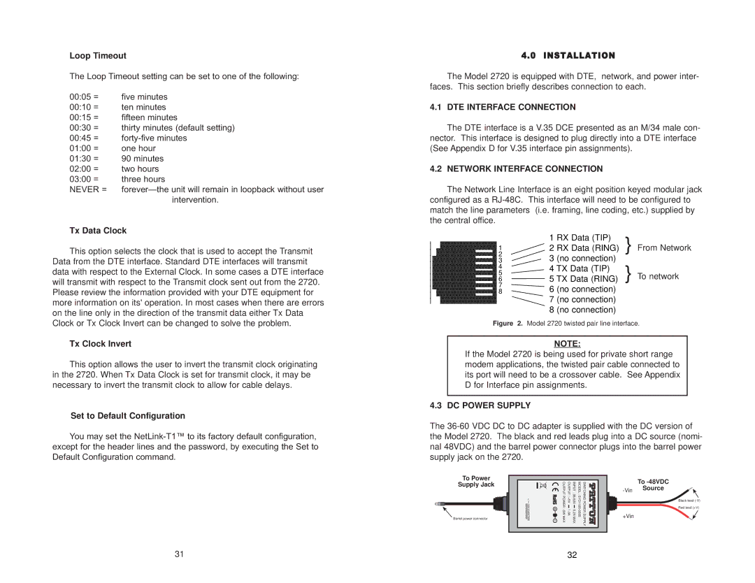
The Network Line Interface is an eight position keyed modular jack configured as a RJ-48C. This interface will need to be configured to match the line parameters (i.e. framing, line coding, etc.) supplied by the central office.


1

RX Data (TIP)

} From Network


2

RX Data (RING)

1


2


3

(no connection)


3


} To network


4


4

TX Data (TIP)


5


5

TX Data (RING)


6


7


6

(no connection)


8


7

(no connection)


8

(no connection)


Figure

2. Model 2720 twisted pair line interface.

NOTE:

If the Model 2720 is being used for private short range modem applications, the twisted pair cable connected to its port will need to be a crossover cable. See Appendix D for Interface pin assignments.

4.3 DC POWER SUPPLY

The 36-60 VDC DC to DC adapter is supplied with the DC version of the Model 2720. The black and red leads plug into a DC source (nomi- nal 48VDC) and the barrel power connector plugs into the barrel power supply jack on the 2720.

To Power

Supply Jack

Barrel power connector

MADEINCHINABYSUNNY

:G01234567890S/N

OUTPUTPOWER:5WMAX

OUTPUT:+5V1.0A

INPUT:36-60V0.2AMAX

MODEL:SYD1106-0505

SWITCHINGPOWERSUPPLY


To -48VDC

-Vin

Source


+Vin


Black lead (-V)

Red lead (+V)

31

32

Page 17
Image 17
Patton electronic 2720/I Series user manual DTE Interface Connection, Network Interface Connection, DC Power Supply

2720/I Series specifications

The Patton Electronic 2720/I Series is a cutting-edge solution designed for businesses seeking reliable and high-performance network connectivity. This series provides a range of features tailored to meet the demands of modern telecommunications, making it ideal for both enterprises and service providers.

One of the standout features of the 2720/I Series is its ability to support multiple protocols, making it versatile for various networking environments. It supports both E1 and T1 interfaces, facilitating seamless integration with different types of communication lines. This adaptability ensures that users can maintain a consistent and efficient communication system, regardless of their existing infrastructure.

The 2720/I Series incorporates advanced technologies that enhance its performance and reliability. Notably, it features robust error detection and correction capabilities, which are essential for preserving data integrity during transmission. This is particularly important in business applications where data loss or corruption can have significant repercussions.

Security is another critical aspect of the 2720/I Series. With built-in encryption support, it ensures that sensitive data remains protected during transit. This makes the series suitable for organizations that handle confidential information and prioritize security in their communication channels.

The 2720/I Series also stands out with its user-friendly management interface. Administrators can easily configure and monitor the devices through a web-based interface, simplifying the management process and minimizing downtime. This intuitive design allows for quick adjustments and troubleshooting, which is vital for maintaining optimal network performance.

Power over Ethernet (PoE) capability is another significant feature of the 2720/I Series. This technology allows the device to receive power through the same cable used for data transmission, reducing clutter and simplifying installation. The ability to deliver power to remote devices enhances the deployment flexibility and efficiency.

In terms of physical characteristics, the 2720/I Series is designed for durability and reliability. It is housed in a rugged casing that can withstand various environmental conditions, making it suitable for deployment in challenging environments.

Overall, the Patton Electronic 2720/I Series combines versatility, reliability, and advanced technology, making it a valuable asset for any organization looking to enhance its communication infrastructure. Its robust features and user-friendly management capabilities make it a preferred choice for managing complex networking challenges effectively.