Patton electronic 2720/I Series ESF Carrier Loops Enabled default Options Enabled, Disabled

Models: 2720/I Series

1 23
Download 23 pages 57.01 Kb
Page 12
Image 12

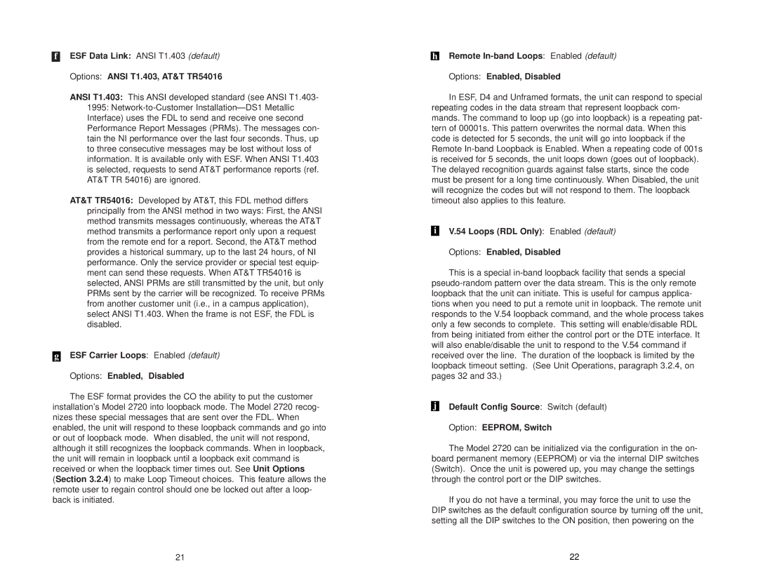
fESF Data Link: ANSI T1.403 (default)

Options: ANSI T1.403, AT&T TR54016

ANSI T1.403: This ANSI developed standard (see ANSI T1.403- 1995: Network-to-Customer Installation—DS1 Metallic Interface) uses the FDL to send and receive one second Performance Report Messages (PRMs). The messages con- tain the NI performance over the last four seconds. Thus, up to three consecutive messages may be lost without loss of information. It is available only with ESF. When ANSI T1.403 is selected, requests to send AT&T performance reports (ref. AT&T TR 54016) are ignored.

AT&T TR54016: Developed by AT&T, this FDL method differs principally from the ANSI method in two ways: First, the ANSI method transmits messages continuously, whereas the AT&T method transmits a performance report only upon a request from the remote end for a report. Second, the AT&T method provides a historical summary, up to the last 24 hours, of NI performance. Only the service provider or special test equip- ment can send these requests. When AT&T TR54016 is selected, ANSI PRMs are still transmitted by the unit, but only PRMs sent by the carrier will be recognized. To receive PRMs from another customer unit (i.e., in a campus application), select ANSI T1.403. When the frame is not ESF, the FDL is disabled.

gESF Carrier Loops: Enabled (default)

Options: Enabled, Disabled

The ESF format provides the CO the ability to put the customer installation’s Model 2720 into loopback mode. The Model 2720 recog- nizes these special messages that are sent over the FDL. When enabled, the unit will respond to these loopback commands and go into or out of loopback mode. When disabled, the unit will not respond, although it still recognizes the loopback commands. When in loopback, the unit will remain in loopback until a loopback exit command is received or when the loopback timer times out. See Unit Options (Section 3.2.4) to make Loop Timeout choices. This feature allows the remote user to regain control should one be locked out after a loop- back is initiated.

hRemote In-band Loops: Enabled (default)

Options: Enabled, Disabled

In ESF, D4 and Unframed formats, the unit can respond to special repeating codes in the data stream that represent loopback com- mands. The command to loop up (go into loopback) is a repeating pat- tern of 00001s. This pattern overwrites the normal data. When this code is detected for 5 seconds, the unit will go into loopback if the Remote In-band Loopback is Enabled. When a repeating code of 001s is received for 5 seconds, the unit loops down (goes out of loopback). The delayed recognition guards against false starts, since the code must be present for a long time continuously. When Disabled, the unit will recognize the codes but will not respond to them. The loopback timeout also applies to this feature.

iV.54 Loops (RDL Only): Enabled (default)

Options: Enabled, Disabled

This is a special in-band loopback facility that sends a special pseudo-random pattern over the data stream. This is the only remote loopback that the unit can initiate. This is useful for campus applica- tions when you need to put a remote unit in loopback. The remote unit responds to the V.54 loopback command, and the whole process takes only a few seconds to complete. This setting will enable/disable RDL from being initiated from either the control port or the DTE interface. It will also enable/disable the unit to respond to the V.54 command if received over the line. The duration of the loopback is limited by the loopback timeout setting. (See Unit Operations, paragraph 3.2.4, on pages 32 and 33.)

jDefault Config Source: Switch (default)

Option: EEPROM, Switch

The Model 2720 can be initialized via the configuration in the on- board permanent memory (EEPROM) or via the internal DIP switches (Switch). Once the unit is powered up, you may change the settings through the control port or the DIP switches.

If you do not have a terminal, you may force the unit to use the DIP switches as the default configuration source by turning off the unit, setting all the DIP switches to the ON position, then powering on the

21

22

Page 12
Image 12
Patton electronic 2720/I Series user manual ESF Carrier Loops Enabled default Options Enabled, Disabled

2720/I Series specifications

The Patton Electronic 2720/I Series is a cutting-edge solution designed for businesses seeking reliable and high-performance network connectivity. This series provides a range of features tailored to meet the demands of modern telecommunications, making it ideal for both enterprises and service providers.

One of the standout features of the 2720/I Series is its ability to support multiple protocols, making it versatile for various networking environments. It supports both E1 and T1 interfaces, facilitating seamless integration with different types of communication lines. This adaptability ensures that users can maintain a consistent and efficient communication system, regardless of their existing infrastructure.

The 2720/I Series incorporates advanced technologies that enhance its performance and reliability. Notably, it features robust error detection and correction capabilities, which are essential for preserving data integrity during transmission. This is particularly important in business applications where data loss or corruption can have significant repercussions.

Security is another critical aspect of the 2720/I Series. With built-in encryption support, it ensures that sensitive data remains protected during transit. This makes the series suitable for organizations that handle confidential information and prioritize security in their communication channels.

The 2720/I Series also stands out with its user-friendly management interface. Administrators can easily configure and monitor the devices through a web-based interface, simplifying the management process and minimizing downtime. This intuitive design allows for quick adjustments and troubleshooting, which is vital for maintaining optimal network performance.

Power over Ethernet (PoE) capability is another significant feature of the 2720/I Series. This technology allows the device to receive power through the same cable used for data transmission, reducing clutter and simplifying installation. The ability to deliver power to remote devices enhances the deployment flexibility and efficiency.

In terms of physical characteristics, the 2720/I Series is designed for durability and reliability. It is housed in a rugged casing that can withstand various environmental conditions, making it suitable for deployment in challenging environments.

Overall, the Patton Electronic 2720/I Series combines versatility, reliability, and advanced technology, making it a valuable asset for any organization looking to enhance its communication infrastructure. Its robust features and user-friendly management capabilities make it a preferred choice for managing complex networking challenges effectively.