Connecting the Twisted Pair (120 ohm) to the G.703 Network
Refer to the pinout and signals chart in Figure 6 to connect the
NETWORK SIGNAL | SIGNAL | PIN# | |||||
RX(R) |
|
|
| TX(R) | 4 | ||
|
|
| |||||
RX(T) |
|
|
| TX(T) | 5 | ||
|
|
| |||||
TX(R) |
|
|
|
| RX(R) | 1 | |
|
|
|
| ||||
TX(T) |
|
|
|
| RX(T) | 2 | |
|
|
|
| ||||
Shield |
|
|
| Shield | 3 | ||
|
|
| |||||
Shield |
|
|
| Shield | 6 | ||
|
|
| |||||
|
| Signal Name | |||
|
| 1 | 1 | (RX) Receive (Ring) | |
|
| 2 | (RX) Receive (Tip) | ||
| |||||
|
| 2 | 3 | Shield | |
| |||||
|
| 3 |
| 4 | (TX) Transmit (Ring) |
|
| ||||
|
| 4 |
| ||
|
|
| 5 | (TX) Transmit (Tip) | |
|
|
|
| ||
5 |
| ||||
|
|
| |||
66 Shield
77 No connection
88 No connection
Figure 6. G.703 120-ohm connection.
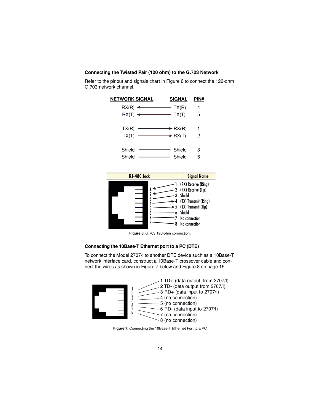
Connecting the 10Base-T Ethernet port to a PC (DTE)
To connect the Model 2707/I to another DTE device such as a
1
2
3
4
5
6
7
8
1 TD+ (data output from 2707/I)
2 TD- (data output from 2707/I)
3 RD+ (data input to 2707/I)
4 (no connection)
5 (no connection)
6 RD- (data input to 2707/I)
7 (no connection)
8 (no connection)
Figure 7. Connecting the 10Base-T Ethernet Port to a PC
14