PL
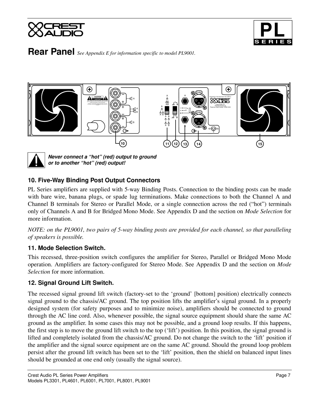
Rear Panel See Appendix E for information specific to model PL9001.
CAUTION
RISK OF ELECTRIC SHOCK
DO NOT OPEN
AVIS : RISQUE DE CHOC ÉLECTRIQUE—NE PAS OUVRIR

 A
A
Designed & manufactured in the USA by:
WARNING TO REDUCE THE RISK OF FIRE OR ELECTRIC SHOCK DO NOT
EXPOSE THIS EQUIPMENT TO RAIN OR MOISTURE.
ATTENTION! POUR ÉVITER LE RISQUE D'INCENDIE OU DE CHOC ÉLECTRIQUE, NE PLACEZ PAS CET APPAREIL SOUS LA PLUIE OU Á L'HUMIDITÉ
Crest Audio Inc.
100 Eisenhower Dr.
Paramus, New Jersey 07652 USA
Never connect a “hot” (red) output to ground or to another “hot” (red) output!
10. Five-Way Binding Post Output Connectors
PL Series amplifiers are supplied with 5-way Binding Posts. Connection to the binding posts can be made with bare wire, banana plugs, or spade lug terminations. Make connections to both the Channel A and Channel B terminals for Stereo or Parallel Mode, or a single connection across the red (“hot”) terminals only of Channels A and B for Bridged Mono Mode. See Appendix D and the section on Mode Selection for more information.
NOTE: on the PL9001, two pairs of 5-way binding posts are provided for each channel, so that paralleling of speakers is possible.
11. Mode Selection Switch.
This recessed, three-position switch configures the amplifier for Stereo, Parallel or Bridged Mono Mode operation. Amplifiers are factory-configured for Stereo Mode. See Appendix D and the section on Mode Selection for more information.
12. Signal Ground Lift Switch.
The recessed signal ground lift switch (factory-set to the ‘ground’ [bottom] position) electrically connects signal ground to the chassis/AC ground. The top position lifts the amplifier’s signal ground. In a properly designed system (for safety purposes and to minimize noise), amplifiers should be connected to ground through the AC line cord. Also, whenever possible, the signal source equipment should share the same AC ground as the amplifier. In some cases this may not be possible, and a ground loop results. If this happens, the first step is to move the ground lift switch to the top (‘lift’) position. In this position, the signal ground is lifted and completely isolated from the chassis/AC ground. Do not change the switch to the ‘lift’ position if the amplifier and the signal source equipment are on the same AC ground. Should the ground loop problem persist after the ground lift switch has been set to the ‘lift’ position, then the shield on balanced input lines should be grounded at one end only (usually the signal source).
Crest Audio PL Series Power Amplifiers | Page 7 |
Models PL3301, PL4601, PL6001, PL7001, PL8001, PL9001 | |