PV 3800 specifications
The Peavey PV 3800 is a powerful and versatile amplifier designed for professional audio applications. It is particularly popular among musicians, DJs, and sound reinforcement professionals who need reliable performance in various settings. This amplifier is known for its robust build quality and exceptional sound reproduction, making it a trusted choice in the world of live sound.One of the standout features of the PV 3800 is its impressive power output. With 3,800 watts of peak power, this amplifier can easily drive large speaker systems, delivering clear and powerful audio even at high volumes. It provides 1,900 watts at 4 ohms in stereo mode, which ensures that it can handle demanding audio environments without distortion or loss of clarity.
Additionally, the PV 3800 is equipped with Peavey’s patented DDT speaker protection circuit. This technology helps prevent speaker damage by automatically detecting when the amplifier is being driven beyond its limits and adjusting the output accordingly. This feature is invaluable for live performances, where fluctuations in sound levels can occur, and it protects both the amplifier and the connected speakers.
Another key characteristic of the PV 3800 is its dual-channel design, which allows for multiple audio sources to be amplified simultaneously. Each channel features its own independent volume control and input options, providing flexibility for a variety of audio setups. Whether used in a simple two-speaker system or a complex multi-speaker arrangement, the PV 3800 can adapt to the specific needs of the user.
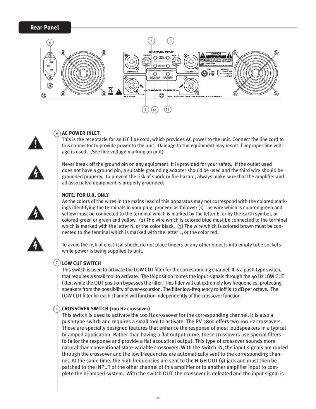
The amplifier's rear panel includes extensive connectivity options, such as XLR and 1/4-inch inputs, making it compatible with a wide range of audio equipment. Additionally, the PV 3800 features a fan-cooled design that helps maintain optimal operating temperatures during long performances, ensuring reliability and longevity.
In terms of size, the PV 3800 is notably portable, allowing for easy transport between gigs. Its durable construction means it can withstand the rigors of touring and live use, making it an excellent investment for professionals who need gear that can keep up with their demanding schedules.
In summary, the Peavey PV 3800 stands out for its powerful performance, innovative technologies, and user-friendly features. With its ability to deliver high-quality audio in a reliable and robust package, it continues to be a popular choice among audio professionals looking for a dependable amplifier.