23.MASTER L/R FADERS:
This is the master level control for the L and R signals sent to the Left and Right Output jacks. When in Main/Monitor mode [see System Mode Switch (19)] the Monitor Fader controls the monitor signal present at the Left/Mon Power Amp Output (4). The Left and Right Faders would then control the L/R Mix present at the Right/L+R Power Amp Output (4). The nominal position for this control is the 0 dB position.
CHANNEL FUNCTIONS
The CHANNEL FUNCTIONS section describes the controls and input connections for each channel of the XR 800F+. Most features are found on all channels, however, there are some differences in channel’s 7, 8 and 9. Therefore, this section is divided to properly indicate those differences.
CHANNELS 1-6
![]()
![]() 24
24

![]() 25
25
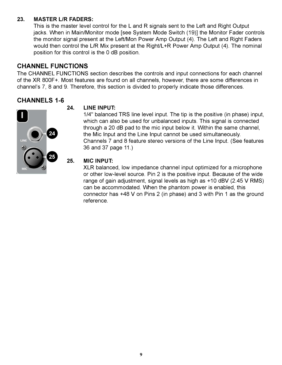
24.LINE INPUT:
1/4" balanced TRS line level input. The tip is the positive (in phase) input, which can also be used for unbalanced inputs. This signal is connected through a 20 dB pad to the mic input below it. Within the same channel, the Mic Input and the Line Input cannot be used simultaneously. Channels 7 and 8 feature stereo versions of the Line Input. (See features 36 and 37 page 11.)
25.MIC INPUT:
XLR balanced, low impedance channel input optimized for a microphone or other
9