SUAC9000 specifications
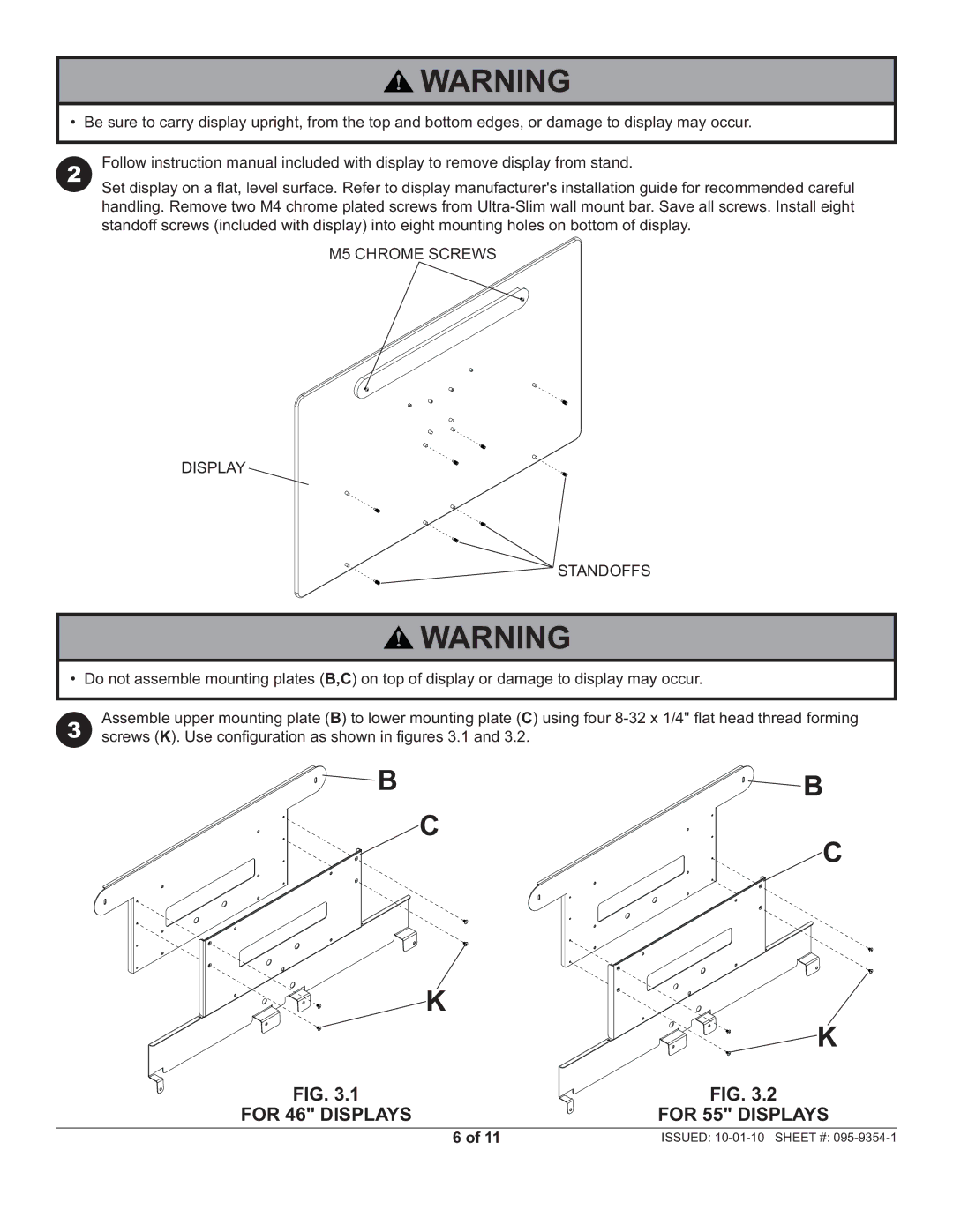
Peerless Industries has long been a trusted name in the audio-visual mounting and display solutions sector. Among its impressive lineup, the Peerless SUAC9000 stands out as a versatile and innovative mount designed specifically for flat-panel displays. This product exemplifies the brand’s commitment to quality, functionality, and user convenience.The SUAC9000 features a sleek and modern design that complements a variety of environments, from corporate settings to educational institutions and homes. One of its main characteristics is its universal compatibility, which supports a wide range of display sizes and brands. This makes it a go-to solution for numerous installation needs, whether for a small conference room or a larger auditorium.
One of the standout technologies incorporated into the SUAC9000 is the easy-to-use mounting mechanism. The mount utilizes a unique Quick-Connect design, enabling swift and secure setup. This feature minimizes the time and effort involved in installation, allowing users to confidently mount their displays with ease. Additionally, the mount offers multiple adjustments to ensure optimal viewing angles. This includes tilt, pan, and swivel capabilities, allowing users to customize the display's orientation to suit the environment and audience's needs.
Moreover, the SUAC9000 is designed with durability in mind. Its robust construction ensures that it can safely support heavy displays while maintaining stability and security. The mount is crafted from high-quality materials that resist wear and tear, ensuring a long lifespan and consistent performance.
Another notable characteristic of the SUAC9000 is its cable management system. This feature allows for a clutter-free installation, as it neatly conceals wires and cables, thereby enhancing the overall aesthetic of the display setup. This attention to detail not only improves the appearance of the installation but also promotes safety by reducing the risk of tripping over unsecured cables.
In conclusion, the Peerless Industries SUAC9000 is a sophisticated mount that marries function with aesthetics. With its universal compatibility, ease of installation, adjustable viewing angles, durability, and effective cable management, the SUAC9000 is ideal for those seeking a reliable and visually appealing solution for mounting flat-panel displays. Whether in a professional or personal setting, this mount undoubtedly enhances the viewing experience while maintaining a tidy and modern look.

