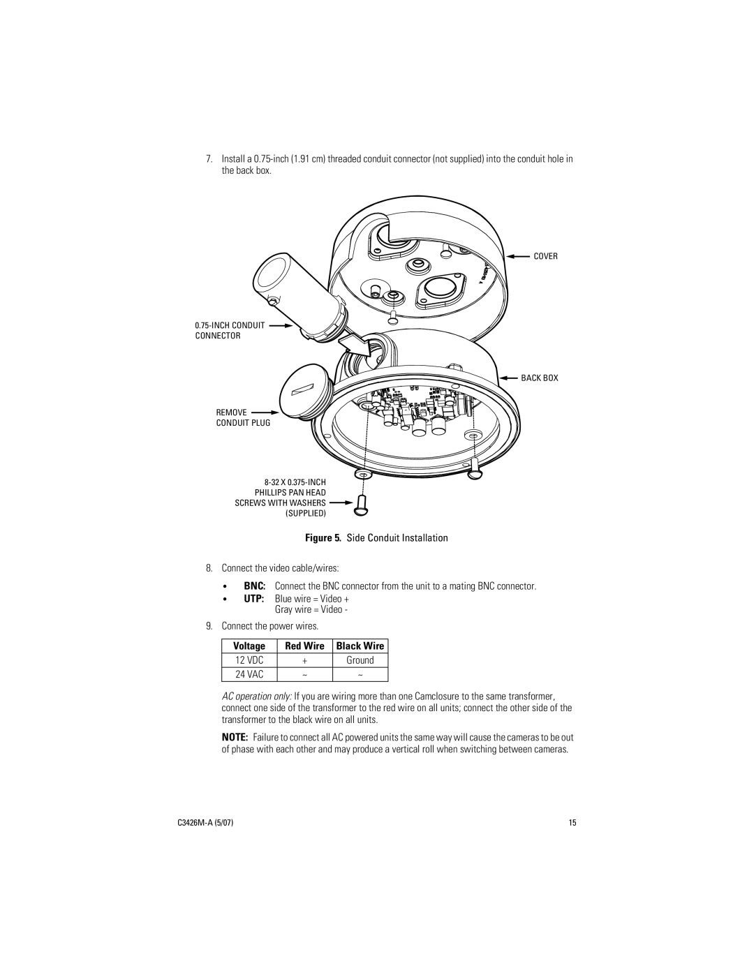
C3426M-A (5/07) specifications
The Pelco C3426M-A is a high-performance pan-tilt-zoom (PTZ) camera designed for versatile surveillance applications in a range of environments. Introduced in 2007, it has garnered attention for its combination of advanced technologies and robust build quality, making it an ideal choice for both indoor and outdoor security needs.One of the key features of the C3426M-A is its 26x optical zoom lens. This powerful zoom capability allows the camera to capture high-quality images from significant distances, making it suitable for perimeter security, monitoring large areas, or focusing on specific objects or events. Coupled with advanced digital zoom options, the camera ensures that even fine details can be captured clearly without sacrificing image quality.
The camera utilizes Pelco’s proprietary technologies to enhance its performance in varying light conditions. With a wide dynamic range and low lux capabilities, it delivers exceptional image clarity in both bright and low-light environments. This adaptability is crucial for surveillance scenarios where lighting conditions can change rapidly.
In terms of build quality, the C3426M-A is designed to withstand harsh environmental conditions. Its rugged housing is weather-resistant, making it suitable for outdoor installations. This durability ensures reliable operation in challenging weather conditions, including rain, snow, and extreme temperatures.
The camera is also equipped with advanced motion detection and programmability features. Users have the ability to set specific areas of interest and configure the camera to respond to motion, which helps to minimize false alarms and optimize monitoring efficiency. The flexibility of programmable presets allows operators to focus on critical areas, enhancing overall surveillance strategy.
Networking capabilities are another highlight of the C3426M-A. Featuring support for various video formats, it easily integrates into existing security systems. The camera can be controlled remotely, allowing for real-time monitoring and adjustments from anywhere, which is particularly advantageous for large facilities or multi-site operations.
In summary, the Pelco C3426M-A (5/07) stands out as a reliable and sophisticated PTZ solution. Its powerful optical zoom, weather-resistant design, advanced imaging technologies, and robust networking capabilities make it an excellent choice for a wide range of security and surveillance applications. Whether for commercial, industrial, or institutional use, this camera offers the flexibility and performance required to meet modern security challenges.

