NOTE: The tilt limit stops are not adjustable.
CAUTION: Do not re- move or reposition the fixed limit stop. Damage will occur.
NOTE:
WARNING: Failure to install the gasket properly will void the warranty.
3.Models with 355° Rotation Only - Adjust the pan limit stops:
a.Pan the unit to the desired left position.
b.Turn off the power.
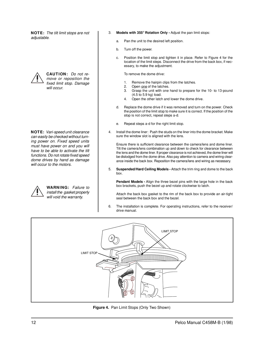
c.Position the limit stop and tighten it in place. Refer to Figure 4 for the location of the limit steps. Disconnect the drive from the back box, if nec- essary, to make the adjustment.
To remove the dome drive:
1.Remove the hairpin clips from the latches.
2.Open one of the latches.
3.Grasp the unit with one hand to prepare for the 10- to
4.Open the other latch and lower the dome drive.
d.Replace the dome drive if it was removed and turn on the power. Check the position of the limit stop to make sure it is correct. If the position of the stop is not correct, repeat steps
e.Repeat steps
4.Install the dome liner: Push the studs on the liner into the dome bracket. Make sure the window slot is aligned with the lens.
Ensure there is sufficient clearance between the camera/lens and dome liner. Tilt the camera/lens combination up and down to check for clearance between the lens and the dome liner. If proper clearance is not achieved, the dome liner will be dislodged from the dome drive. Also pay attention to camera and wiring clear- ance inside the back box. Reposition the camera/lens and wiring as necessary.
5.Suspended/Hard Ceiling Models - Attach the trim ring and dome to the back box.
Pendant Models - Align the three bezel pins with the large hole in the back box brackets, push the bezel up and rotate clockwise to latch.
Attach the back box gasket to the rim of the back box to provide an
6.The installation is complete. For operating instructions, refer to the receiver/ drive manual.
LIMIT STOP
LIMIT STOP
Figure 4. Pan Limit Stops (Only Two Shown)
12 | Pelco Manual |