OUTPUT CONNECTIONS
Perform the following steps to attach 24 VAC devices to the MCS*E Series power supply:
1.Refer to Tables C and D in this manual or the wiring table on the unit’s lid to determine the output connection needed for your devices.
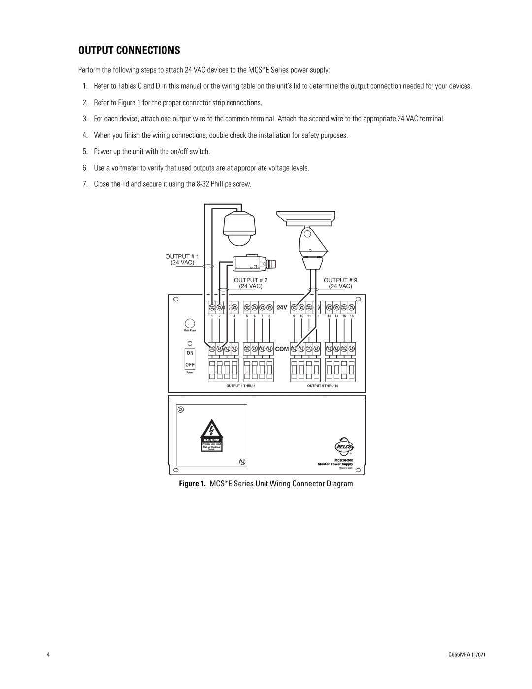
2.Refer to Figure 1 for the proper connector strip connections.
3.For each device, attach one output wire to the common terminal. Attach the second wire to the appropriate 24 VAC terminal.
4.When you finish the wiring connections, double check the installation for safety purposes.
5.Power up the unit with the on/off switch.
6.Use a voltmeter to verify that used outputs are at appropriate voltage levels.
7.Close the lid and secure it using the
OUTPUT # 1
(24 VAC)
|
|
| OUTPUT # 2 |
|
|
|
|
| OUTPUT # 9 | ||||||
|
|
|
| (24 VAC) |
|
|
|
|
| (24 VAC) | |||||
|
|
|
|
|
|
|
| 24V |
|
|
|
|
|
|
|
1 | 2 | 3 | 4 | 5 | 6 | 7 | 8 | 9 | 10 | 11 | 12 | 13 | 14 | 15 | 16 |
Main Fuse
ON
![]()
![]()
![]()
![]()
![]() COM
COM ![]()
![]()
![]()
![]()
![]()
![]()
![]()
![]()
![]()
OFF
Power
OUTPUT 1 THRU 8 | OUTPUT 9 THRU 16 |
Figure 1. MCS*E Series Unit Wiring Connector Diagram
4 |