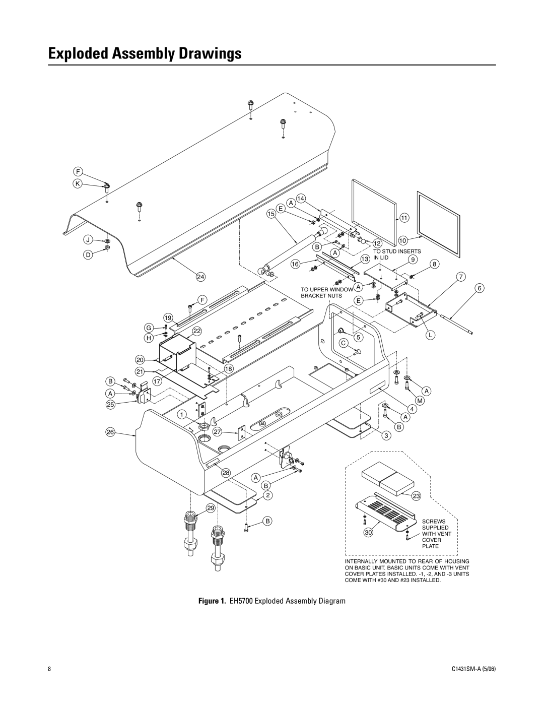
EH5700 Series specifications
The Pelco EH5700 Series is a cutting-edge line of environmental housings designed for high-performance video surveillance in challenging outdoor conditions. Engineered to protect cameras and associated equipment, these housings ensure longevity and reliability while maintaining exceptional image quality.One of the standout features of the EH5700 Series is its robust construction. Made from lightweight yet durable materials, these housings are designed to withstand harsh weather conditions, including extreme temperatures, rain, snow, and high winds. The housing is also equipped with an IP66 rating, confirming its resistance to dust and water ingress, making it ideal for use in a variety of environments.
The EH5700 Series utilizes advanced technologies to support a range of surveillance applications. It is compatible with various camera types, offering flexibility for users to install their preferred models. The series supports both fixed and PTZ (pan-tilt-zoom) cameras, making it versatile for different security needs. The housing also includes a heater and blower system, which operates efficiently to maintain optimal operating temperatures for sensitive electronic components, ensuring peak performance in both high-heat and cold environments.
Additionally, the EH5700 Series features built-in cable management systems, simplifying the installation process while ensuring that cables are organized and well-protected from environmental elements. This contributes to a professional appearance and enhances the overall reliability of the system.
The housing is designed for easy access, allowing for straightforward installation, maintenance, and upgrades. It's equipped with locking mechanisms to secure the enclosed equipment, providing peace of mind for users concerned about theft or tampering.
In terms of characteristics, the EH5700 Series encompasses a sleek and unobtrusive design, allowing it to blend seamlessly into various architectural styles without drawing undue attention. This aesthetic consideration is particularly important for installations in urban settings where visual impact must be minimized.
Overall, the Pelco EH5700 Series combines innovative design, robust construction, and advanced features to deliver a superior environmental housing solution tailored for the needs of modern video surveillance systems. Its commitment to reliability, performance, and adaptability makes it an excellent choice for security professionals seeking to protect their investments in surveillance technology.

