IMPORTANT SAFETY INSTRUCTIONS
READ AND FOLLOW ALL INSTRUCTIONS BEFORE OPERATING SYSTEM
Operating the PG2000
Refer to the toggle switch position diagram below for the appropriate switch positions for your particular installation.
The switches are located on the lower right side of the unit. The PG2000 should always operate in manual mode no matter what type of control system is installed.
NOTE
When cycling system off, then back on, it may take up to
![]() CAUTION
CAUTION
PG2000 Illuminator must have good ventilation to operate properly. Blockage of air flow or air intake will shorten the bulb life and could damage the unit. Make sure foliage; grass, groundcover, yard debris, etc. is kept clear of intake vents on back of the unit in order to allow for proper air flow. Do not install PG2000 Illuminator in an underground utility box or similar appliance. Damage to the unit due to blocked air vents or poor ventilation will void the warranty.
Replacing the Bulb.
1. Turn power to unit off.
![]() WARNING
WARNING
Turn off power before changing bulb. Failure to turn off power may lead to severe electrical shock, which can result in death or severe injury.
2.Remove two screws securing outer body and lift outer body straight up.
TOGGLE SWITCH POSITIONS
MANUAL CONTROL
POWER | COLOR | POWER | COLOR |
OFF | OFF | ON | ON |
REMOTE SWITCH CONTROL | RF2000 WIRELESS CONTROL | ||
POWER COLOR | POWER | COLOR |
![]() WARNING
WARNING
Bulb socket, and reflector are extremely hot during and following operation. Allow sufficient time for cooling before touching them, or you may suffer severe burns.
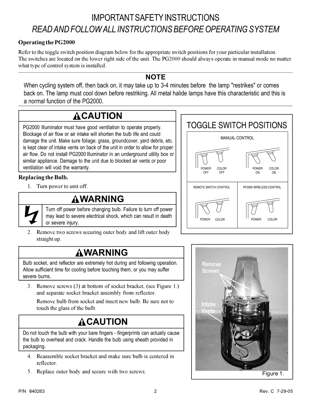
3.Remove screws (3) at bottom of socket bracket, (see Figure 1.) and separate socket bracket assembly from reflector.
Remove bulb from socket and insert new bulb. Be sure not to touch the glass of the bulb.
![]() CAUTION
CAUTION
Do not touch the bulb with your bare fingers - fingerprints can actually cause the bulb to overheat and crack. Handle the bulb using sheath provided in packaging.
4.Reassemble socket bracket and make sure bulb is centered in reflector.
5.Replace outer body and secure with two screws.
Remove
Screws
Intake
Vents
Figure 1.
P/N 840263 | 2 | Rev. C |
