Note:
Note:
Caution!
Refer to Chapter 13 “Specifications”, for detail on input sensitivity and impedance.
Please set the input configuration switch ![]() to the appropriate setting.
to the appropriate setting.
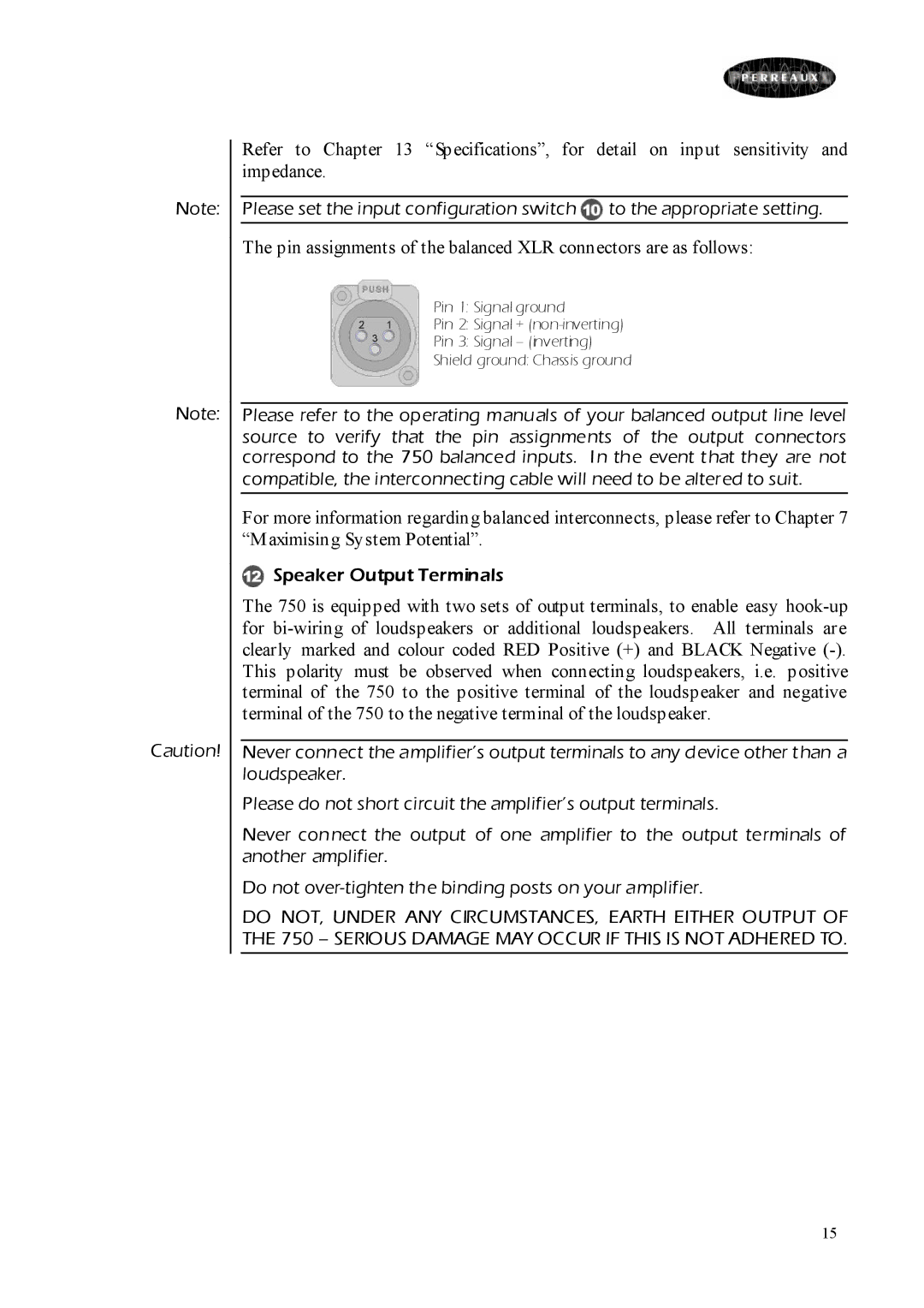
The pin assignments of the balanced XLR connectors are as follows:
Pin 1: Signal ground
Pin 2: Signal +
Pin 3: Signal – (inverting)
Shield ground: Chassis ground
Please refer to the operating manuals of your balanced output line level source to verify that the pin assignments of the output connectors correspond to the 750 balanced inputs. In the event that they are not compatible, the interconnecting cable will need to be altered to suit.
For more information regarding balanced interconnects, please refer to Chapter 7 “Maximising System Potential”.
 Speaker Output Terminals
The 750 is equipped with two sets of output terminals, to enable easy
Never connect the amplifier’s output terminals to any device other than a loudspeaker.
Please do not short circuit the amplifier’s output terminals.
Never connect the output of one amplifier to the output terminals of another amplifier.
Do not
DO NOT, UNDER ANY CIRCUMSTANCES, EARTH EITHER OUTPUT OF THE 750 – SERIOUS DAMAGE MAY OCCUR IF THIS IS NOT ADHERED TO.
15
