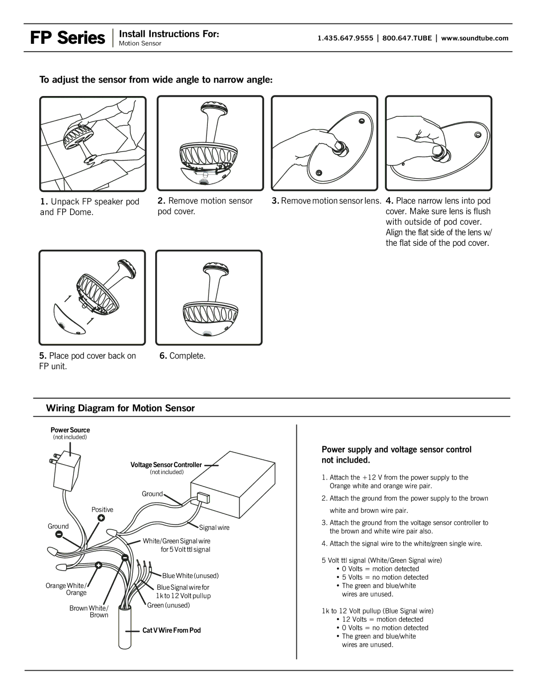
FP Series specifications
The Phase Technology FP Series is a line of high-performance loudspeakers that promise to enhance the listening experience across a variety of environments. Designed for audiophiles, home theater enthusiasts, and music lovers alike, the FP Series encapsulates advanced audio technologies and thoughtful engineering to deliver exceptional sound quality and performance.One of the primary features of the FP Series is its unique driver configuration. These loudspeakers utilize a combination of high-quality woofers and tweeters that are meticulously engineered to work in harmony. The woofers are designed to produce deep, rich bass, while the tweeters are optimized for clear, detailed high frequencies. This configuration ensures a balanced sound that captures the full range of audio, making music and movie soundtracks come alive.
The cabinet design of the FP Series is another standout characteristic. Each speaker is housed in a rigid, acoustically inert enclosure that minimizes unwanted vibrations and enhances sound clarity. The enclosures are often crafted from high-quality materials, ensuring durability without compromising on aesthetics. The sleek design not only blends well with modern interiors but also facilitates optimal sound dispersion.
Incorporating innovative technologies is a hallmark of the FP Series. One such technology is the use of phase-coherent crossover networks, which ensure a seamless transition between drivers. This results in a coherent soundstage where individual instruments and voices can be distinctly heard within the mix, creating an immersive listening experience.
Moreover, the FP Series speakers are engineered for versatility. They can be utilized in various settings, whether it’s a dedicated home theater, a living room, or a professional studio. Their ability to handle various power levels also allows them to be paired with a wide range of amplifiers without distortion, making them an excellent choice for different audio setups.
In summary, the Phase Technology FP Series stands out with its exceptional driver configuration, robust cabinet design, and innovative technologies. These characteristics combine to offer a listening experience that is both dynamic and nuanced, catering to the demands of discerning users. Whether enjoying a concert recording or a cinematic masterpiece, the FP Series speakers promise to deliver audio that is true to its source and rich in detail. For those looking to elevate their sound experience, the Phase Technology FP Series may well be the ideal solution.

