BDL3220QL
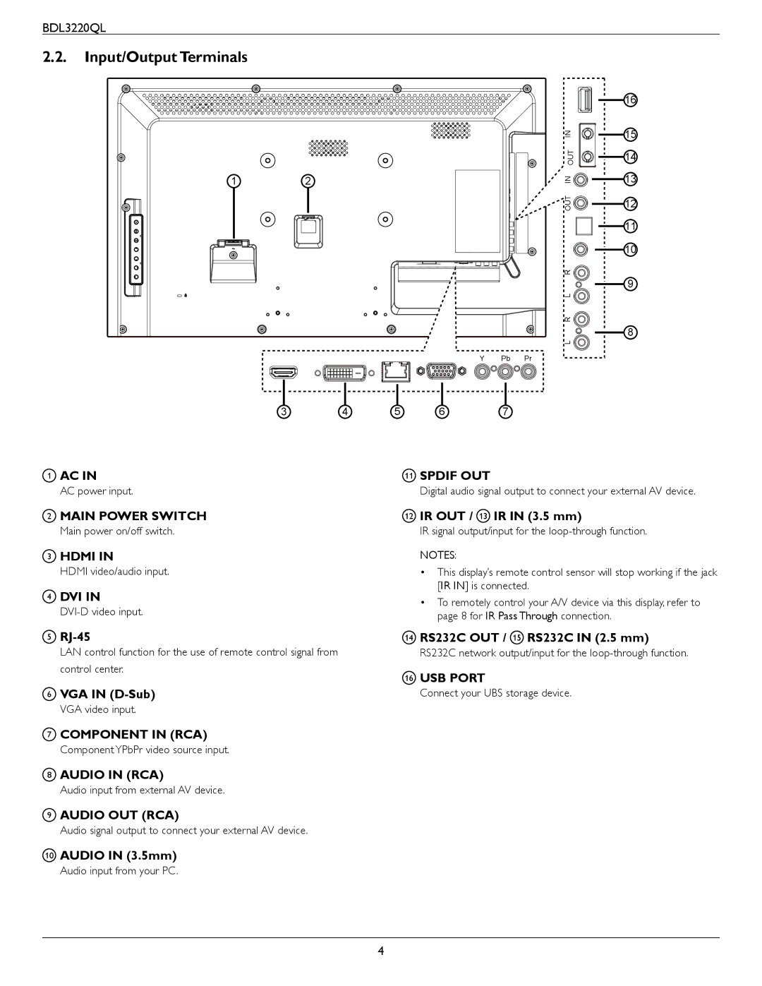
2.2.Input/Output Terminals
12
3 4
1AC IN
AC power input.
2MAIN POWER SWITCH
Main power on/off switch.
3HDMI IN
HDMI video/audio input.
4DVI IN
5
LAN control function for the use of remote control signal from control center.
6VGA IN
VGA video input.
7COMPONENT IN (RCA)
Component YPbPr video source input.
8AUDIO IN (RCA)
Audio input from external AV device.
9AUDIO OUT (RCA)
Audio signal output to connect your external AV device.
10AUDIO IN (3.5mm)
Audio input from your PC.
| 16 |
IN | 15 |
OUT | 14 |
| |
IN | 13 |
OUT | 12 |
| 11 |
| 10 |
R |
|
L | 9 |
| |
R |
|
L | 8 |
|
Y Pb Pr
5 | 6 | 7 |
11SPDIF OUT
Digital audio signal output to connect your external AV device.
12IR OUT / 13 IR IN (3.5 mm)
IR signal output/input for the
NOTES:
•This display’s remote control sensor will stop working if the jack [IR IN] is connected.
•To remotely control your A/V device via this display, refer to page 8 for IR Pass Through connection.
14RS232C OUT / 15 RS232C IN (2.5 mm)
RS232C network output/input for the
16USB PORT
Connect your UBS storage device.
4