4
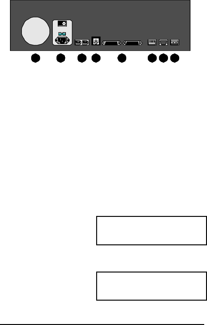
1.4 Rear Panel Diagram 1 2 3 4 5 6 7 8
Rear Panel Elements
1. Cooling Fan: Do not obstruct.
2. Power Connector, Voltage Selector and On/Off Switch
3. IEEE-1394 Firewire Ports 1 and 2*
4. 10/100 Ethernet Port*
5. SCSI Ports 1 and 2
6. Dip Switches*
7. RS-232 Port
8. Alarm Out Relay Connection*
NOTE:
* The Ethernet, Aux dip switch, Alarm output and IEEE-1394 Firewire ports are
reserved for future upgrade.
SCSI Ports 1 and 2
Connect to either SCSI port. Using
the dip switches on the rear of the
unit, set SCSI Termination and
SCSI Power to On.
Connector: 50 pin, high density SCSI-2.
Gender (on unit): Female.
SCSI ID: 0.
The unit does not currently support multiple SCSI device connections.
RS-232 Port
The RS-232 port is used for flash
upgrading the DVAA operating
system software.
Connector Type: DB-9.
Gender (on unit): Male.
Cable Required: Null Modem.