Product Information
RETURN TO TOP OF THE PAGE
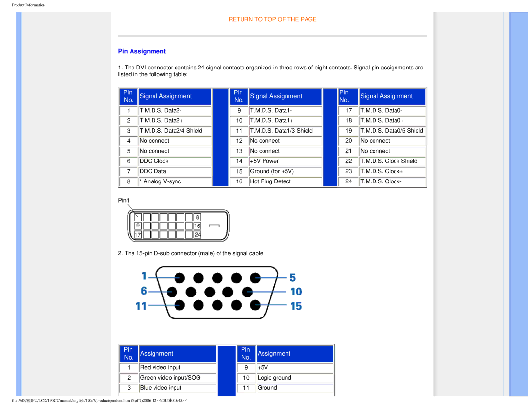
Pin Assignment
1.The DVI connector contains 24 signal contacts organized in three rows of eight contacts. Signal pin assignments are listed in the following table:
|
|
|
|
|
|
|
|
|
|
|
|
|
|
|
|
|
| Pin |
| Signal Assignment |
| Pin |
| Signal Assignment |
| Pin |
| Signal Assignment |
| ||||
| No. |
|
|
|
| No. |
|
|
|
| No. |
|
| |||
1 |
| T.M.D.S. Data2- |
|
| 9 |
| T.M.D.S. Data1- |
|
| 17 |
| T.M.D.S. Data0- | ||||
2 |
| T.M.D.S. Data2+ |
|
| 10 |
| T.M.D.S. Data1+ |
|
| 18 |
| T.M.D.S. Data0+ | ||||
3 |
| T.M.D.S. Data2/4 Shield |
|
| 11 |
| T.M.D.S. Data1/3 Shield |
|
| 19 |
| T.M.D.S. Data0/5 Shield | ||||
4 |
| No connect |
|
| 12 |
| No connect |
|
| 20 |
| No connect | ||||
5 |
| No connect |
|
| 13 |
| No connect |
|
| 21 |
| No connect | ||||
6 |
| DDC Clock |
|
| 14 |
| +5V Power |
|
| 22 |
| T.M.D.S. Clock Shield | ||||
7 |
| DDC Data |
|
| 15 |
| Ground (for +5V) |
|
| 23 |
| T.M.D.S. Clock+ | ||||
8 |
| * Analog |
|
| 16 |
| Hot Plug Detect |
|
| 24 |
| T.M.D.S. Clock- | ||||
|
|
|
|
|
|
|
|
|
|
|
|
|
|
|
|
|
2. The
|
|
|
|
|
|
|
|
|
|
|
| Pin |
| Assignment | Pin |
| Assignment |
| |||
|
|
|
|
|
| |||||
| No. |
|
|
|
| No. |
|
| ||
1 |
| Red video input |
|
| 9 |
| +5V | |||
2 |
| Green video input/SOG |
|
| 10 |
| Logic ground | |||
3 |
| Blue video input |
|
| 11 |
| Ground | |||
|
|
|
|
|
|
|
|
|
|
|
file:///D/EDFU/LCD/190C7/manual/english/190c7/product/product.htm (5 of