SETUP (Continued)

SETTING THE ALARM

The ALARM function allows the user to set the recording duration, speed to be recorded and tape recycle for alarm recordings. When a contact clos- ure occurs at the ALARM IN input, the VCR auto- matically enters the RECORD mode at the pre-pro- grammed ALARM recording speed. (See Alarm In, page 10 for a complete description of the ALARM sequence.) The ALARM recording duration can last according to the set value, or until the contact clos- ure is reopened.

The ALARM recording speed can be pre-pro- grammed to 08, 24 or 40.

The checking signal is automatically recorded on the tape at the beginning of each ALARM recording. Later, you can easily locate the start of each record- ing by using these signals when watching a re- corded content. See “ALARM INDEX SEARCH” on page 23 for details.

See page 14 if you also want to record the date/time. The TIME/DATE display is set as follows during ALARM display.

ALARM stars () will replace the colons (:).

The recording speed will be changed to 08, 24 or 40 which was selected from the “SPEED” setting in the ALARM display.

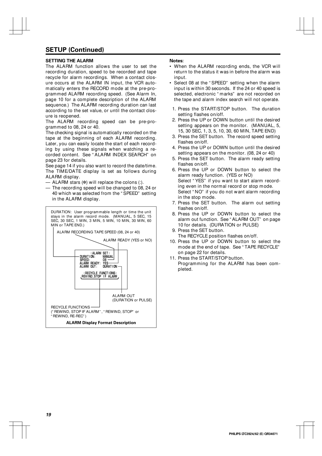
DURATION: User programmable length or time the unit stays in the alarm record mode. (MANUAL, 5 SEC, 15 SEC, 30 SEC, 1 MIN, 3 MIN, 5 MIN, 10 MIN, 30 MIN, 60 MIN or TAPE END.)

ALARM RECORDING TAPE SPEED (08, 24 or 40)

ALARM READY (YES or NO)

ALARM SET

DURAT I ON:

MANUAL

SPEED :

08

ALARM READY : YES

ALARM OUT :

DURAT I ON

RECYCLE

FUNCT I ONS

REW I ND , STOP I F ALARM

ALARM OUT (DURATION or PULSE)

RECYCLE FUNCTIONS

(“REWIND, STOP IF ALARM”, “REWIND, STOP” or “REWIND, RE-REC”)

ALARM Display Format Description

Notes:

When the ALARM recording ends, the VCR will return to the status it was in before the alarm was input.

Select 08 at the “SPEED” setting when the alarm input is within 30 seconds. If the 24 or 40 speed is selected, electronic “marks” are not recorded on the tape and alarm index search will not operate.

1.Press the START/STOP button. The duration setting flashes on/off.

2.Press the UP or DOWN button until the desired setting appears on the monitor. (MANUAL, 5, 15, 30 SEC, 1, 3, 5, 10, 30, 60 MIN, TAPE END)

3.Press the SET button. The record speed setting flashes on/off.

4.Press the UP or DOWN button until the desired setting appears on the monitor. (08, 24 or 40)

5.Press the SET button. The alarm ready setting flashes on/off.

6.Press the UP or DOWN button to select the alarm ready function. (YES or NO)

Select “YES” if you want to start alarm record- ing even in the normal record or stop mode. Select “NO” if you do not want alarm recording in the stop mode.

7.Press the SET button. The alarm out setting flashes on/off.

8.Press the UP or DOWN button to select the alarm out function. See “ALARM OUT” on page 10 for details. (DURATION or PULSE)

9.Press the SET button.

The RECYCLE position flashes on/off.

10.Press the UP or DOWN button to select the mode at the end of tape. See “TAPE RECYCLE” on page 22 for details.

11.Press the START/STOP button.

Programming for the ALARM has been com- pleted.

19

PHILIPS LTC3924/62 (E) QR34071

Page 20
Image 20
Philips LTC 3924, LTC 3962 manual Alarm Display Format Description

LTC 3924, LTC 3962 specifications

Philips LTC 3962 and LTC 3924 are two prominent LED drivers designed to enhance lighting efficiency and performance in various applications. These devices stand out for their innovative technology and key features, making them ideal choices for both residential and commercial lighting solutions.

The Philips LTC 3962 is a high-performance LED driver that offers a wide input voltage range, catering to various lighting designs. It supports constant current output, ensuring stable lighting performance over time and aiding in superior color consistency across LED arrays. With its compact design, the LTC 3962 is well-suited for applications requiring space-efficient solutions. Notably, it features built-in thermal protection and supports dimming options, allowing users to adjust brightness levels according to their preferences and energy-saving needs.

On the other hand, the Philips LTC 3924 is designed for higher power applications, enabling it to drive larger LED arrays effectively. It boasts advanced power management technologies, which enhance energy efficiency by minimizing losses during operation. The LTC 3924 supports dimmable LED drivers, while its robust architecture accommodates a wide variety of LED types, ensuring flexibility for design engineers. One of the standout characteristics of the LTC 3924 is its ability to interface seamlessly with smart lighting systems, paving the way for enhanced connectivity and control.

Both the LTC 3962 and LTC 3924 integrate advanced features such as over-voltage, under-voltage, and over-current protection, ensuring reliable performance in varying conditions. They also come with built-in diagnostic features, which allow for easy troubleshooting and maintenance, thus extending the lifespan of the LED lighting systems they power.

In summary, Philips LTC 3962 and LTC 3924 are exceptional LED drivers, engineered with innovative technologies and features that cater to the evolving needs of modern lighting. Their emphasis on efficiency, flexibility, and reliability makes them ideal candidates for a wide range of applications, ensuring optimal performance in any setting. Whether for smart homes, commercial spaces, or industrial environments, these LED drivers represent a significant advancement in lighting technology, driving the future of energy-efficient illumination.