1.FASTEN THE PROJECTOR MOUNT TO 1 ½”NPT PIPE
1:The bracket must be secured to a ceiling structure capable of at least (4) times the weight of the projector + mount.
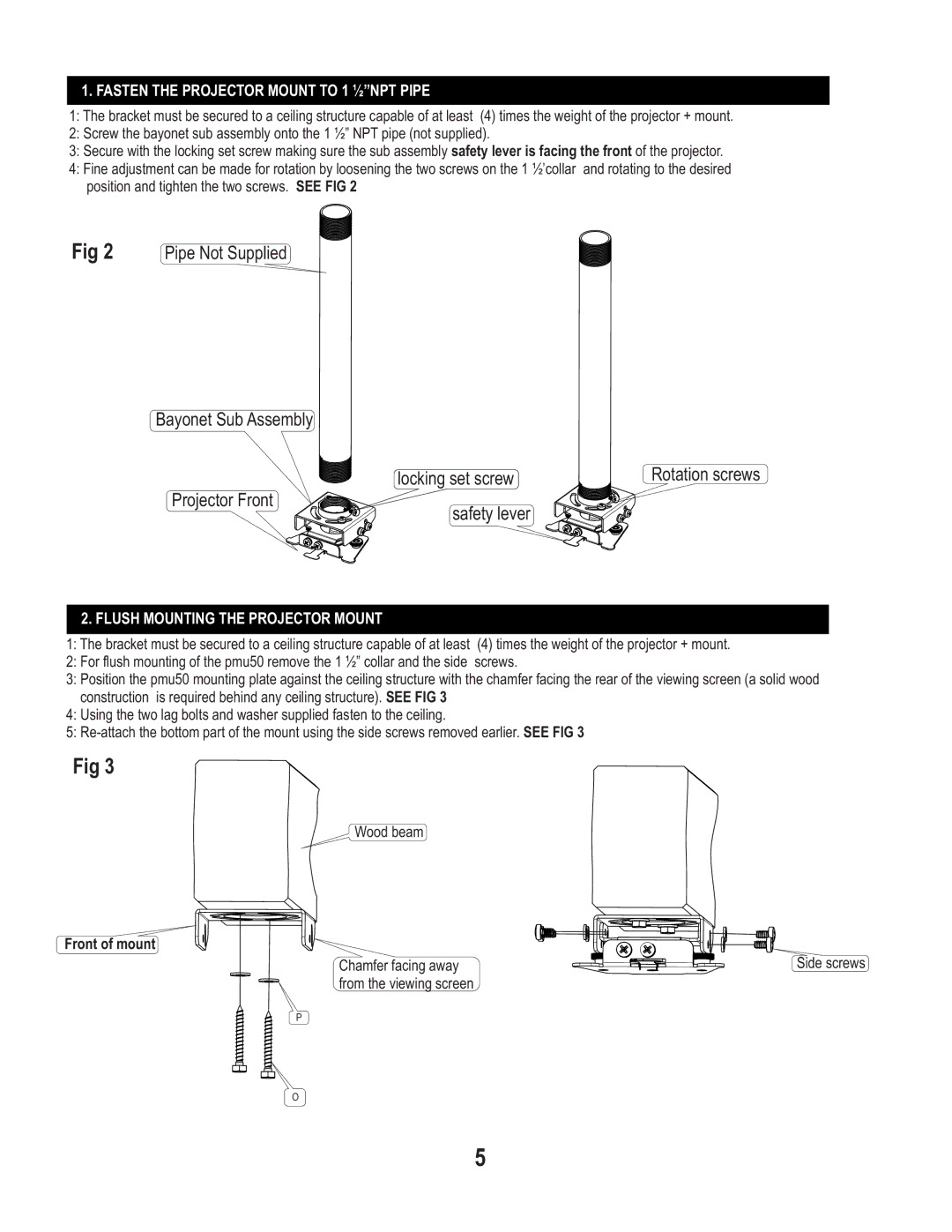
2:Screw the bayonet sub assembly onto the 1 ½” NPT pipe (not supplied).
3:Secure with the locking set screw making sure the sub assembly safety lever is facing the front of the projector.
4:Fine adjustment can be made for rotation by loosening the two screws on the 1 ½’collar and rotating to the desired position and tighten the two screws. SEE FIG 2
Fig 2 Pipe Not Supplied
Bayonet Sub Assembly
locking set screw | Rotation screws |
Projector Front
safety lever
2.FLUSH MOUNTING THE PROJECTOR MOUNT
1:The bracket must be secured to a ceiling structure capable of at least (4) times the weight of the projector + mount.
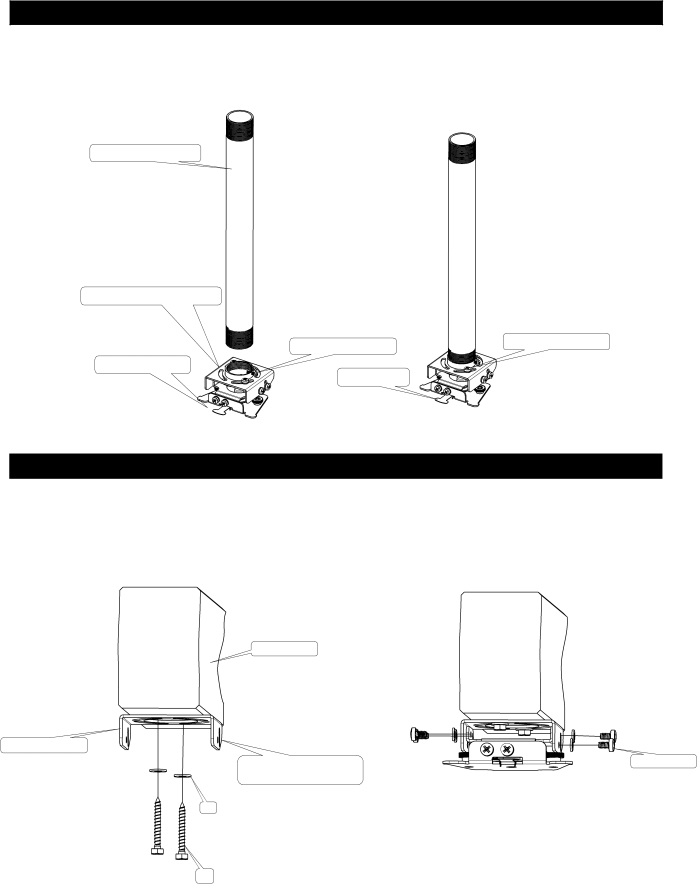
2:For flush mounting of the pmu50 remove the 1 ½” collar and the side screws.
3:Position the pmu50 mounting plate against the ceiling structure with the chamfer facing the rear of the viewing screen (a solid wood construction is required behind any ceiling structure). SEE FIG 3
4:Using the two lag bolts and washer supplied fasten to the ceiling.
5:
Fig 3
Wood beam
Front of mount
Chamfer facing away | Side screws |
from the viewing screen |
|
P
O
5