3.ATTACH THE ADAPTER PLATE TO THE PROJECTOR.
1:Start by screwing the leveling barrels ( A ) into the Adjustable arms (K and L). A screwdriver slot is provided in the barrel (A). The barrels only need to be threaded approx. 1/8“ through the bottom of the arm (K and L). If the mounting plane of the projector is not flat, the barrels can be adjusted to make up the difference in height. SEE FIG 1
2:Using the adapter plate ( M ) attach the adjustable arms ( K,L ) with the hardware supplied (B,C,F). No need to tighten at this time. SEE FIG 1
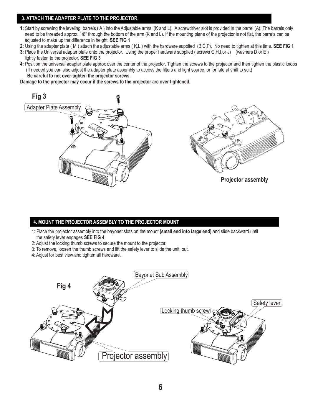
3: Place the Universal adapter plate onto the projector. Using the proper hardware supplied ( screws G,H,I,or J) (washers D or E ) lightly fasten to the projector. SEE FIG 3
4:Position the universal adapter plate approx over the center of the projector. Tighten the screws to the projector and then tighten the plastic knobs (If needed you can also adjust the adapter plate assembly to access the filters and light source, or for lateral shift to suit)
Be careful to not
Damage to the projector may occur if the screws to the projector are over tightened.
Fig 3
Adapter Plate Assembly
Projector assembly
4.MOUNT THE PROJECTOR ASSEMBLY TO THE PROJECTOR MOUNT
1:Place the projector assembly into the bayonet slots on the mount (small end into large end) and slide backward until the safety lever engages SEE FIG 4.
2:Adjust the locking thumb screws to secure the mount to the projector.
3:To remove, loosen the thumb screws and lift the safety lever to slide the unit out.
4:Adjust for best view and tighten all hardware.
Bayonet Sub Assembly
Fig 4
Safety lever
Locking thumb screw
Projector assembly
6