Amplifier Owner’s Manual
Z500.4
4 CHANNEL POWER AMPLIFIER
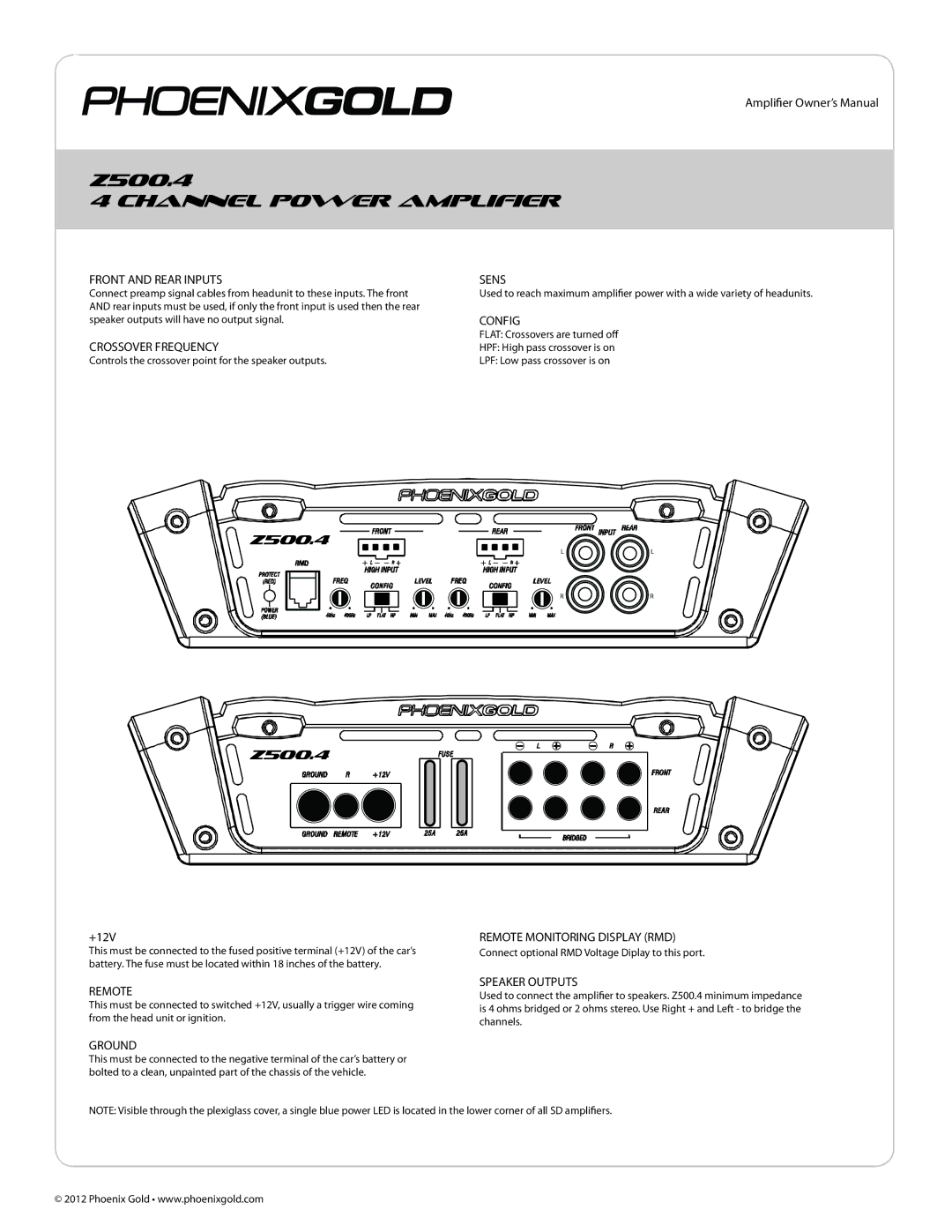
FRONT AND REAR INPUTS
Connect preamp signal cables from headunit to these inputs. The front AND rear inputs must be used, if only the front input is used then the rear speaker outputs will have no output signal.
CROSSOVER FREQUENCY
Controls the crossover point for the speaker outputs.
SENS
Used to reach maximum amplifier power with a wide variety of headunits.
CONFIG
FLAT: Crossovers are turned off
HPF: High pass crossover is on
LPF: Low pass crossover is on
 Z500.4
LL
RR
![]() Z500.4
Z500.4
+12V | REMOTE MONITORING DISPLAY (RMD) |
This must be connected to the fused positive terminal (+12V) of the car’s | Connect optional RMD Voltage Diplay to this port. |
battery. The fuse must be located within 18 inches of the battery. |
|
REMOTE
This must be connected to switched +12V, usually a trigger wire coming from the head unit or ignition.
SPEAKER OUTPUTS
Used to connect the amplifier to speakers. Z500.4 minimum impedance is 4 ohms bridged or 2 ohms stereo. Use Right + and Left - to bridge the channels.
GROUND
This must be connected to the negative terminal of the car’s battery or bolted to a clean, unpainted part of the chassis of the vehicle.
NOTE: Visible through the plexiglass cover, a single blue power LED is located in the lower corner of all SD amplifiers.
© 2012 Phoenix Gold • www.phoenixgold.com