6
PicoScope 2000 Series User Guide
input impedance is also standard, so the x10 function on scope probes works correctly.
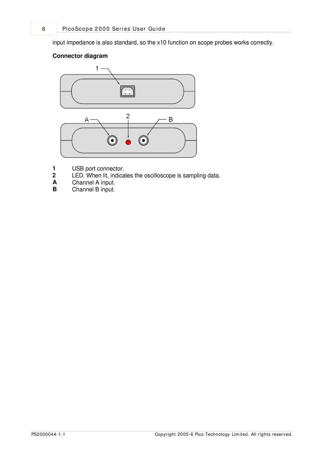
Connector diagram
1USB port connector.
2LED. When lit, indicates the oscilloscope is sampling data.
AChannel A input.
BChannel B input.
Copyright |