Manuals
/
Pico Communications
/
Computer Equipment
/
Power Supply
Pico Communications
PICOPSU-90
installation instructions
Typical configuration
Models:
PICOPSU-90
1
2
4
4
Download
4 pages
22.89 Kb
1
2
3
4
Install
Warranty
Typical configuration
Page 2
Image 2
Page 1
Page 3
Page 2
Image 2
Page 1
Page 3
Contents
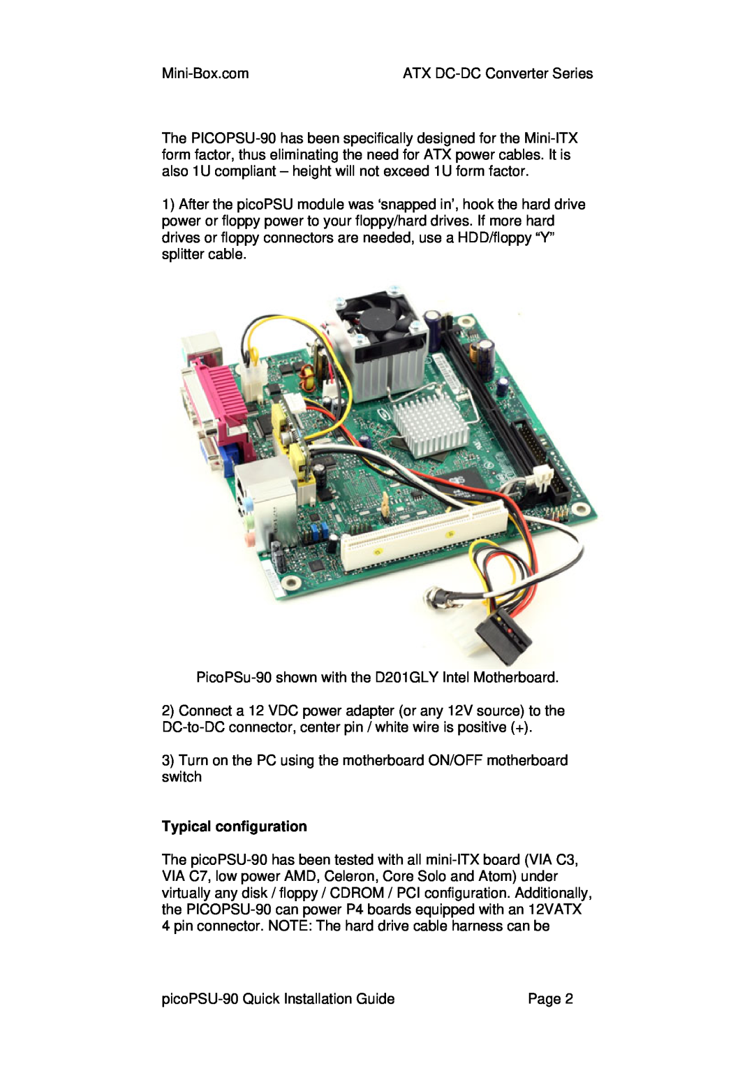
picoPSU-90
Quick Installation Guide
12V, 90Watt ATX Power Supply
Typical configuration
Page
Turn-on Delay
Warranty
Overload protection
Remote ON/OFF control PSON
Top
Page
Image
Contents