MPC12R.qxd 7/7/06 10:46 AM Page 7
Installation Procedure
MPC-12R
Installation
It is recommended that assistance be available to safely install equipment in equipment racks. Chassis must be fastened securely in equipment rack before populating with modules.
1.Install chassis in equipment rack (equipment rack sold separately) by sup- porting the bottom and rear of chassis at the desired elevation in rack.
2.Line up the side holes of chassis with the tapped equipment rack holes
3.Insert the provided screws through the side holes in chassis and thread into the tapped equipment rack holes.
4.Fasten the bottom screws first, then fasten top screws, tighten securely.
5.Slide power supply and equipment modules into chassis.
6.Connect power supply to all modules before supplying line power to the power supply.
7.Connect modules as described in the manual associated with module.
MODULE REPLACEMENT
1.Power Supply:
•Remove power supply by sliding the unit out the front of the chassis.
•Insert replacement power supply into chassis.
2.Modules:
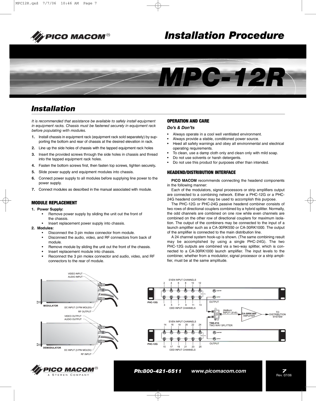
•Disconnect the 3 pin molex connector from module.
•Disconnect the audio, video, and RF connectors from back of module.
•Remove module by sliding the unit out the front of the chassis.
•Insert replacement module into chassis.
•Reconnect the 3 pin molex connector and audio, video, and RF connectors to the rear of module.
OPERATION AND CARE
Do’s & Don’ts
•Always operate in a cool well ventilated environment.
•Always provide a stable, conditioned power source.
•Heed all safety warnings and obey all environmental and electrical operating requirements.
•To clean, use a damp cloth only and clean only with mild soap.
•Do not use solvents or harsh detergents.
•Do not use this product for purposes other than intended.
HEADEND/DISTRIBUTION INTERFACE
PICO MACOM recommends connecting the headend components in the following manner:
Each of the modulators, signal processors or strip amplifiers output are connected to a combining network. Either a
The
A 24 channel system
7 |
Rev. 07/06