DVR-220DVR-320
LASERPRODUCTCLASS1
POWER-CORD Caution
Operating Environment
Contents
Resetting the recorder
Setting up the remote to control your TV
Additional information
Index
Features
Before you start
Before you start Chapter
Before you start
Putting the batteries in the remote control
Using the remote control
Before you start What’s in the box
General disc compatibility
DVD-R/RW compatibility
CD-R/RW compatibility
Compressed audio compatibility
WMA Windows Media Audio compatibility
Jpeg file compatibility
PC-created disc compatibility
Original
Connecting up
Connecting up Chapter
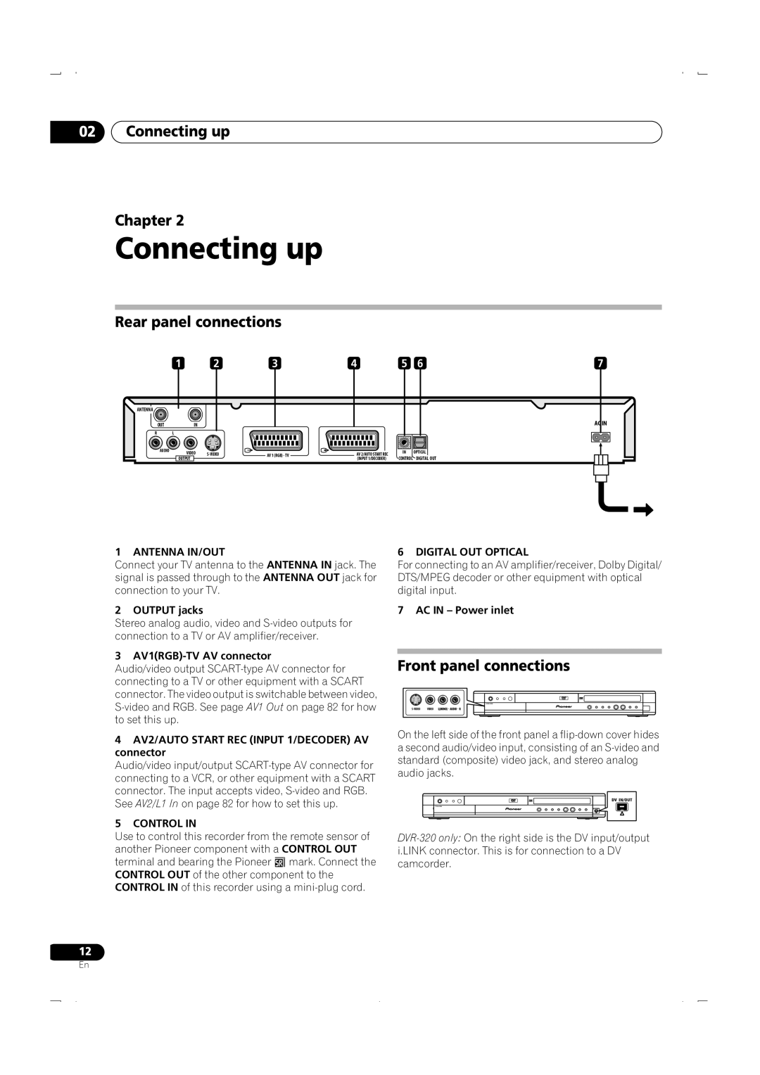
Rear panel connections
Front panel connections
Connecting up Extra features for use with compatible TVs
Connecting up Easy connections
Connecting up Using other types of audio/video output
Connect the Video Output jack to a video input on your TV
This enables you to watch and record TV channels
This enables you to watch discs
This enables you to record scrambled TV channels
Connect RF antenna cables as shown
Connecting up Connecting an external decoder box
Scart AV Connector
Connecting up Connecting to an AV amplifier/receiver
This enables you to listen to multichannel surround sound
Connecting up Connecting other AV sources
Plugging
Controls and displays
Controls and displays Chapter
Front panel
STANDBY/ON
Controls and displays Display
Controls and displays Remote control
Audio
Subtitle
Angle
Controls and displays
Switching on and setting up
Getting started
Getting started Chapter
Enter
Getting started
Other settings you can make
Select the TV screen type, ‘Standard 43’ or ‘Wide 169’
Connected, or Not Connected, then press Enter
Digital, Dolby Digital, DTS or PCM only, then press
Using the built-in TV tuner
Getting started Making your first recording
Playing back your recording
Changing TV channels
Switching between TV and DVD
Basic playback
Changing audio channels
Nicam
Press STANDBY/ON to switch on
Playing DVD discs
Press OPEN/CLOSE to open the disc tray Load a disc
To stop playback, press Stop
Playing CDs and WMA/MP3 discs
Playing Video CD/Super VCDs
Using the Home Menu
Displaying disc information on- screen
Stop display
Use
Play display
Recording display
Recording mode
Using the Disc Navigator to browse the contents of a disc
Playback
Playback Chapter
Introduction
Using the Disc Navigator with recordable discs
Playback
Changing the thumbnail picture for a title
Select ‘Play’ from the menu options
Navigating discs
Scanning discs
Scan 1 Scan 2 Scan 3 Scan
Scan Scan 2 Scan
Playing in slow motion
Frame advance/frame reverse
Slow 1/2
Press
Playback Play Mode menu
Search Mode
Play Mode
Repeat
Repeat play
Program play
Other Program play functions
Repeat to build up a program list
Playback Displaying and switching subtitles
Switching DVD soundtracks
Clear
Playback Switching audio channels
Switching camera angles
To display/switch the audio channel, press Audio repeatedly
To switch the camera angle, press Angle
Recording
Recording Chapter
About DVD recording
Recording time and picture quality
Setting the picture quality/recording time
Recording Restrictions on video recording
Recording equipment and copyright
Recording Basic recording from the TV
Load a recordable disc
Front panel display shows the channel number
Use the Audio button to select the audio channel to record
Setting a timer recording
Recording
Direct recording from TV
Easy Timer Recording
Press Easy Timer
Set the TV channel and recording quality
Current time Recording start time
Standard timer recording
Press Timer REC to display the Timer Recording screen
Enter the timer recording settings
Press Enter to set the end time
Timer recording using the Video Plus+ programming system
To exit the timer recording screen, press Home Menu
Video Plus+ programming with the power off
Extending a timer recording in progress
LUS Code
Next
Canceling and stopping a timer recording in progress
Moving the end time by 30-minute blocks
Programming a new end time
Recording Timer recording FAQ
You can’t enter a timer program if the clock isn’t set
See Connecting up for connection options
Simultaneous recording and playback
Set up the recorder
Press REC when you’re ready to start recording
See Audio In settings on page 83 for more on these settings
Automatic recording from a satellite tuner
Also, set the camcorder to VTR mode
Recording from a DV camcorder DVR-320 only
AV2/L1 In is set to Decoder see AV2/L1 In on
Press Home Menu and select ‘DV Record’ from the menu
Recording from the DV output DVR-320 only
Playing your recordings on other DVD players
Finalizing a disc
Press Home Menu and select ‘Disc Setup’ Select ‘Finalize’
How to change the recorder’s setting
Press Home Menu and select ‘Disc Setup’ Select ‘Initialize’
Initializing a DVD-RW disc
Editing
Editing Chapter
Disc Navigator screen
Playlist / Original indicator
Editing
Disc Navigator menu options
Editing Editing VR mode Original and Video mode content
Play
Erase
Title Name Ttl Name
Using the remote key shortcuts to input a name
Chapter Edit Chpt Edit
Editing
Key Characters ’ ?
Inserting chapter markers into a title
Erase Section Erase Sec
Select ‘Erase Sec’ from the Disc Navigator menu options Use
Title
Lock / Unlock
Erase All
Undo
This erases all unlocked titles from the disc see also Lock
Editing Creating and editing a VR mode Play List
You can give titles new names of up to 64 characters long
Press Enter after selecting each character
Input a name on
Create
Original title to put into the Play List
Divide
Move
Combine
Press Enter to add the title
This command erases all the titles from the Play List
Select ‘Undo’ from the Disc Navigator Play List menu options
Using the Disc History
Disc History
Disc History Chapter
PhotoViewer
PhotoViewer Chapter
Playing a slideshow
Reloading files from a disc
PhotoViewer
Zooming the screen
Rotating the screen
Disc Setup menu
Disc Setup menu Chapter
Basic settings
Press Home Menu and select ‘Disc Setup’
Disc Setup menu
Initialize settings
Finalize settings
Video/Audio Adjust menu
Video/Audio Adjust menu Chapter
Setting the picture quality for TV and external inputs
Choosing a preset
Video/Audio Adjust menu
Setting the picture quality for disc playback
Select the picture quality setting you want to adjust
Black Setup setting applies only when playing Ntsc discs
Audio DRC
Initial Setup menu
Initial Setup menu Chapter
Using the Initial Setup menu
Clock Setting
Initial Setup menu
Power Save
Input Line System
On Screen Display
Tuner settings
Remote Control Set
Setup Navigator
Auto Channel Setting Auto Scan
Auto Channel Setting Download from TV
Manual CH Setting
Channel Swapping
Set Video Plus+ CH
Initial Setup menu Video In / Out settings
Input Colour System
AV1 Out
AV2/L1
Audio In settings
Ntsc on PAL TV
Nicam Select
Tuner Level
Audio Out settings
Language settings
Default setting w/Subtitle Language
Subtitle Language
Auto Language
DVD Menu Language
Recording settings
Selecting ‘Other’ languages
Manual Recording
Optimized Rec
Playback settings
Parental Lock Set Password
Parental Lock Change Password
Seamless Playback
Parental Lock
Parental Lock Change Level
Parental Lock Country Code
Angle Indicator
Resetting the recorder
Setting up the remote to control your
Using the TV remote control buttons
Additional information
When viewing on a standard TV or monitor
When viewing on a widescreen TV or monitor
Additional information Screen sizes and disc formats
Additional information Troubleshooting
Problem Remedy
General
Additional information
Frequently asked questions
Problem
Additional information About DV DVR-320 only
DV-related messages
Additional information Language code list
Country code list
Language Language code letter, Language code
Country, Country code, Country code letter
Message
Cleaning the pickup lens
Handling discs
Storing discs
Damaged discs
Hints on installation
Additional information Condensation
Manual recording modes
Moving the recorder
Additional information Glossary
Mpeg video
Optical digital output
PCM Pulse Code Modulation
PBC PlayBack Control Video CD/Super VCD only
Additional information Specifications
Timer
Tuner
Input/Output
Supplied accessories
AV Connectors 21-pin connector assignment
PIN no
Index
Video mode 7, 9, 10, 22, 34, 44, 56, 57, 60, 73, 88, 96
Pioneer Corporation
VRB1335-A