Pioneer PRS-D4000F Installation, Specifications, Connecting the Speakers and Input Wires

Models: PRS-D4000F

1 6
Download 6 pages 43.63 Kb
Page 3
Image 3

Connecting the Unit

<ENGLISH>

Installation

<ENGLISH>

Specifications

<ENGLISH>

Connecting the Speakers and Input Wires

The speaker output mode can be four-channel, three-channel (stereo + mono) or two-channel (stereo, mono). Connect the speaker leads to suit the mode according to the figures shown below.

Two-channel (Stereo)

Input select switch is on the top of the unit. Slide this switch to the left.

RCA input jack A

In the case of two-channel mode

CAUTION

• Do not install in:

—Places where it could injure the driver or pas- sengers if the vehicle stops suddenly.

• Do not install the amplifier on unstable places

such as the spare tire board.

• The best location for installation differs with the

car model and installation location. Secure the

amplifier at a sufficiently rigid location.

• Make temporary connections first and check that

Power source

14.4 V DC (10.8 V to 15.1 V allowable)

Grounding system

Negative type

Current consumption

27.7 A (at continuous power, 4 )

Average current drawn*

10.4 A (4 for four channels)


20.2 A (4 for two channels)


Four-channel

Input select switch is on the top of the unit. For two- channel input, slide this switch to the left. For four- channel input, slide this switch to the right.

RCA input jack A

RCA input jack B

+ ≠≠ +

(Left) Speaker out B (Right)

connect RCA plugs to the RCA input jack A.

Connecting wire with RCA plugs

(sold separately)

From car stereo (RCA output)

+

Speaker (Right)

+

—Places where it may interfere with the driver,

such as on the floor in front of the driver’s seat.

• Make sure that wires are not caught in the sliding

mechanism of the seats, resulting in a short-cir-

cuit.

• Confirm that no parts are behind the panel when

drilling a hole for installation of the amplifier.

Protect all cables and important equipment such

as fuel lines, brake lines and electrical wiring

from damage.

• Install tapping screws in such a way that the screw

tip does not touch any wire. This is important to

prevent wires from being cut by vibration of the

the amplifier and the system operate properly.

• After installing the amplifier, confirm that the

spare tire, jack and tools can be easily removed.

Example of installation on the floor mat or on the chassis

1. Place the amplifier where it is to be

installed. Insert the supplied tapping

screws (4 18 mm) into the screw

holes. Push on the screws with a


20.2 A (2 for four channels)

Fuse

30 A 2

Dimensions

304 (W) 56 (H) 202 (D) mm

Weight

3.0 kg (Leads for wiring not included)

Maximum power output

150 W 4 (4 ) / 600 W 2 (4 )

Continuous power output

75 W 4 (at 14.4 V, 4 , 20 Hz to 20 kHz 1.0%

THD)


300 W 2 (at 14.4 V, 4 , 1 kHz 1.0%

THD)


150 W 4 (at 14.4 V, 2 , 1 kHz 1.0%

THD)

Load impedance

4 (2 to 8 allowable)


(Bridge connection: 4 to 8 allowable)

Frequency response

10 Hz to 40 kHz (+0 dB, –3 dB)

Signal-to-noise ratio

100 dB (IEC-A network)

Distortion

0.005% (10 W, 1 kHz)

Separation

70 dB (1 kHz)

Connecting wires with RCA plugs (sold separately)

From car stereo (RCA output)

If only one input plug is used, such as when the car stereo has only one output (RCA output), connect the plug to RCA input jack A, but do not connect a plug to RCA input jack B.

+ ≠≠ +

(Right) Speaker out A (Left)

Two-channel (Mono)

Input select switch is on the top of the unit. Slide this switch to the left.

RCA input jack A

In the case of two-channel mode connect RCA plugs to the RCA input jack A.

Speaker (Left)

car, which can result in fire.

• DO NOT allow amplifier to come into contact

with liquids due to, for example, the location

where the amplifier is installed. Electrical shock

could result. Also, amplifier and speaker damage,

smoke, and overheating could result from contact

with liquids. In addition, the amplifier surface and

the surface of any attached speakers could become

hot to the touch and minor burns could result.

• To ensure proper installation, use the supplied

parts in the manner specified. If any parts other

than the supplied ones are used, they may damage

screwdriver so they make marks

where the installation holes are to be

located.

2. Drill 2.5 mm diameter holes at the

point marked, and install the ampli-

fier, either on the carpet or directly

to the chassis.

Low pass filter

Cut off frequency: 40 Hz to 120 Hz


Cut off slope: –12 dB/oct

High pass filter

Cut off frequency: 40 Hz to 120 Hz


Cut off slope: –12 dB/oct

Gain control

RCA: 400 mV to 6.5 V


Speaker: 1.6 V to 26 V

Maximum input level / impedance

RCA: 6.5 V / 22 k


Speaker: 26 V / 90 k

Note:

• Specifications and the design are subject to possible modification without notice

Three-channel

Input select switch is on the top of the unit. For two- channel input, slide this switch to the left. For four- channel input, slide this switch to the right.

RCA input jack A

RCA input jack B


Speaker out B

+

(Mono)


Connecting wire with RCA plugs

(sold separately)

From car stereo (RCA output)

+

Speaker (Mono)

+

Speaker (Mono)

internal parts of the amplifier, or they may

become loose causing the amplifier to shut down.

• Never replace the fuse with one of greater value

or rating than the original fuse. Use of an improp-

er fuse could result in overheating and smoke and

could cause damage to the product and injury

including burns.

CAUTION:

To prevent malfunction and/or injury

• To ensure proper heat dissipation of the amplifier,

be sure of the following during installation.

—Allow adequate space above the amplifier for

Replacing the terminal cover

1.Align the unit and terminal cover, and insert the screw.

2.Tighten the screw with a 4 mm hexagonal wrench (not supplied).

Screw

Tapping-screws (4 18 mm)

Terminal Cover

due to improvements.

*Average current drawn

The average current drawn is nearly the maximum current drawn by this unit when an audio signal is input. Use this value when working out total current drawn by multiple power amplifiers.

Connecting wires

with RCA plugs

(sold separately)

From car stereo (RCA output)

If only one input plug is used, such as when the car stereo has only one output (RCA output), connect the plug to RCA input jack A, but do not connect a plug to RCA input jack B.

+ ≠≠ +

(Right) Speaker out A (Left)

proper ventilation.

—Do not cover the amplifier with a floor mat or

carpet.

• DO NOT allow amplifier to come into contact

with liquids due to, for example, the location

where the amplifier is installed. Electrical shock

could result. Also, amplifier and speaker damage,

smoke, and overheating could result from contact

with liquids. In addition, the amplifier surface and

the surface of any attached speakers could become

hot to the touch and minor burns could result.

Floor mat or chassis

Drill a 2.5 mm diameter hole

Page 3
Image 3
Pioneer PRS-D4000F Installation, Specifications, Connecting the Speakers and Input Wires, Replacing the terminal cover

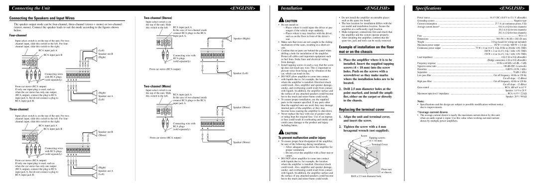
PRS-D4000F specifications

The Pioneer PRS-D4000F is a high-performance car amplifier designed to enhance the audio experience in vehicles. Known for its robust construction and innovative features, this amplifier is an ideal choice for audiophiles seeking to boost their sound system's power and clarity.

One of the standout characteristics of the PRS-D4000F is its impressive power output. It delivers 1,000 watts RMS at 2 ohms, ensuring that even the most demanding speakers receive the necessary power for optimal performance. With a peak power output of up to 4,000 watts, it is capable of driving multiple speakers without strain, providing a rich and immersive listening experience.

The amplifier features a Class D design, which is known for its efficiency and reduced heat production compared to traditional amplifier classes. This design allows the PRS-D4000F to maintain a compact size while still providing impressive power levels. Additionally, this efficiency means that it can be installed in a variety of spaces without worrying about excessive heat buildup, making it versatile for different vehicle types.

Another notable feature of the PRS-D4000F is its adjustable low- and high-pass filters, allowing users to tailor the sound to their preferences. The low-pass filter ensures that subwoofers receive the appropriate frequencies, while the high-pass filter prevents distortion in the midrange and high frequencies. This level of customization is particularly appealing to those who seek a specific sound signature in their audio setup.

The integrated bass boost function is another technology that enhances the performance of the PRS-D4000F. Users can easily adjust the bass output to their liking, giving them control over the low-end response. This feature is especially beneficial for users who enjoy genres of music that rely heavily on bass.

The amplifier is built with advanced thermal management technologies to ensure reliability during extended use. It boasts a robust chassis and heat sinks that keep the unit cool, even under heavy workloads. This durability is critical for ensuring longevity and consistent performance over time.

Additionally, the PRS-D4000F includes multiple protection circuits, safeguarding the amplifier from common issues such as short circuits, overheating, and overloading. This built-in protection offers peace of mind to users, allowing them to enjoy their music without the fear of damaging their equipment.

In summary, the Pioneer PRS-D4000F is an exceptional car amplifier that combines power, efficiency, and user-friendly features. Its Class D design, adjustable filters, bass boost function, and comprehensive protection systems make it a versatile choice for anyone looking to elevate their in-car audio experience. Whether for casual listening or serious audiophile applications, the PRS-D4000F stands out as a reliable and powerful component for any car audio system.