P74M
A F E T YP R E C a U T I O N S
Safetyinformation
XR-P74M, XR-P64M, XR-P34M xR-P7 &, XR-pOaO, XR-P34
XR-P74OM, XR-P64OM, XR-P34OM xR-P7 N, XR-P64, XR-P34
Labetcheck Forcd Multi
CLASS1vrsr8r,ErAsER Laserproduct RA0tATtotwHHrloPtN
Forcd Single
FM/AM tun.r slstion FMTunrrSoction
Specfcations
XR-P74M, XR-P64M, XR-P340M xR-P7 Q, XR-P64, XR-P3@
Receiver
Panelfacilities
XR-P74OM, XR-P64OM, XR-P34OM R-P7 Q. XR-P6@, XR-P34O
XR-P74M, XR-P621M, XR-P34M xR-P7 &, XR-P64, XR-P340
Tapedeck
@oor--ev.NRoN/OFFbuttonXR-P3/o/XR-P3/0Monly
Tapedeck MULTI-PIAYCDPLAYER Cdplayer
Remotecontrolunit O PowER butron @ Functionbutton Funci
6l VOLUME-/+l buttons @ Numberbuttons
XR-P74M, XR-P64M, XR-P340M xR-P7 N, XR-P640, XR-P34
Sleep
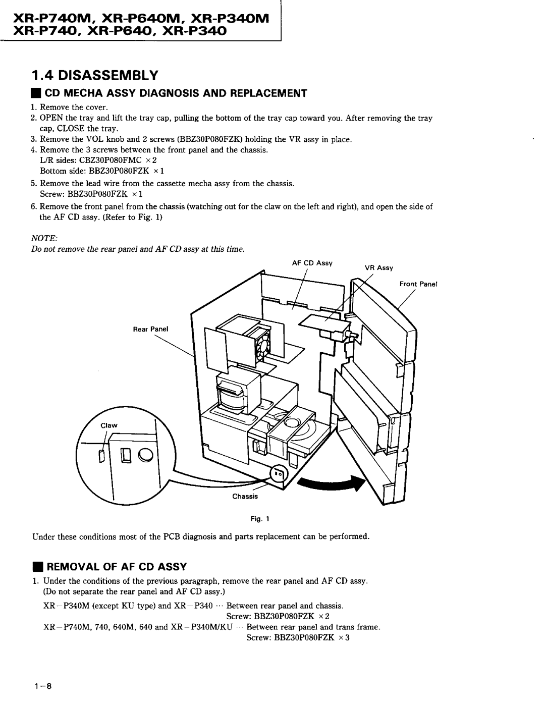
Disassembly
XR-P74M, XR-P640M, XR-P34M xF-P7 40, XR-P640, XR-P34
Blockdiagram
Poweramp Modulesection
XR-P740M, XR-P640M, XR-P340M xR-P740, XR-P64J--,XR-P34.o
OVT l
Pin Functionof Power Amo Module
XR-P740M, XR-P64M, XR-P340M xR-P7 44, XR-P640, XR-P34
Tzv
+t2v
IC Information
XR-P740M, XR-P640M, XR-P34M xR-P7 40, XR-P64trJ, XR-P340
Rc9268F ilc84o1 AF cD AssY
PinAssignment View
XR-P740M, XR-P640M, XR-P340M xR-P7 40, XR-P6 Q, XR-P340
System Control Micro-computer o PinAssignmentTopView
So1
FIPs 7G
XR-P74M, XR-P640M, XR-P34M xR-P7 &, XR-P640, XR-P34
FIP21 P1o/KO3 P
XR-P7@M, XR-P640M, XR-P340M xR-P7 &, XR-P64J, XR-P340
PinAssignmentTop View
60 FIP26 P1s/KO8 P
XR-P74OM, XR-P64OM. XR-P34OM xR-P7 &, XR-P64, XR-P34
PLL9162
XR-P740M, XR-P640M, XR-P34M xR-P7 Q, XR-P64, XR-P340
PDGtoSA ADDoN Iflc3951 DtspLAyAssy
ExceptXR-P34OM and XR-P34Ol
System Control Micro-computer a PinFunction
Dolby OFF
Lnverter PinAssignmentTopView
Outy
TSnnill fltNfifrl\VlltFrll
P7 4OM. XR-P64OM, XR-P34OM xR-P74, XR-P64, XR-P340
N S
KAIRAIKE\
PR@
XR.-P7 4AM, XR-P640M, XR-P340M
XR-P74, XR-P64, XR-P340
Lnvzool v3951 ADDoN DtspLAyAssyl
Adjustments
XR-P7@M, XR-P64OM, XR-P3@M xR-P7 40, XR-P64, XR-P34
Tunersection
FM TunerSection
Poweramp MODULESECTTONReferto Fig .2 1
HandlingPrecautions
Adjustment and Confirmationof ldle Current
XR-P74OM. XR-P64OM, XR.P34OM xR.-P7 4o-, XR-P64HJ,XR-P340
XR-e2461y1, XR-P640M, XR-P34M R-P7 Q, XR-P64O, XR-P34O
RearAmp Side REAR,PWR,PRTECASSY
Remarks
Donot opemteSurroundAmp
XR-P74O/M. XR-P64OM. XR-P34OM xR-P7 4o, XR-P6,4J-,XR-P34
7 E o
CN7
OLiFr
XR-P74OM, XR-P64OM, XR-P34OM xR-P7 40, XR-P640, XR-P34
STD-301
Tape Test
Play
Playback Adjustment HeadAzimuthAdjustment
XR-P74OM, XR-P64OM, XR-P34OM xR-P7 &, XR-P64, XR-P34
Playback
Recording
RecordingLevelAdjustment
XR-P740M, XR-P64M, XR-P34M xR-P7 Q, XR-P64, XR-P34
Recording Adiustmont BiasOscillationFrequencyAdiustment
ALC OperationCheck
Front
DOLBYPRO.LOGICADJUSTMENT 5. Dolbysurroundadjustment
XR-P74o/M, XR-P64M, XR-P34M xR-P7 4o,XR-P6,40,XR-P340
VR8152 Fcsgan
XR-P740M, XR-P64M, XR-P34M xR-P74, XR-P64, XR-P34
CD Sectionforcd Multiand CD Single
Test Point and Adjustment Variable Resistor Positions
Test Mode
XR-P740M, XR-P640M, XR-P340M xR-P740, XR-P64J, XR-P34
\ t Ooo avR81s2 / \
Focus servo close
XR-P74OM, XR-P64OM, XR-P34OM xR-P7 4, XR-P64, XR-P34
Dolbynr
XR-P740M, XR-P640M, XR-P34M xR.-P7 40, XR-P64, XR-P340
REV
Search FWD
Eject
TrackingErrorBalanceVerification
XR-P740M, XR-P64M, XR-P340M xR-P7 &, XR-P64, XR-P34
FocusOffset Verilication
YEDS7
Pickup Radlal/Tangential Titt Adjustmont For GD Multil
LProcedurel
XR-P740M, XR-P640M, XR-P34M xR-P7 40, XR-P64J, XR-P340
Disc
Pictup Radial/Tangential Tilt Adjustment For GD Single
Min of audio signal music.1
XR-P740M, XR-P64M, XR-PS4M xR-P74, XR-P64trJ,XR-P340
Cm disc
Tt l l , ,//Ar
XR-P740M, XR-P64M, XR-P34M xIl.-P7 40, XR-P64, XR-P340
RF Level Verification
Focus Servo Loop Gain Adjustment
P74,.M. XR-P64OM, XR-P34OM xR-P74, XR-P64J--, XR-P34O
CHl
CHz
TrackingServo Loop Gain Adjustment
XR-P7 4oM, XR-P64M, XR-P34M xR-P7 4, XR-P64, XR-P340
CH1
YEDS7
XR-P74M, XR-P640M, XR-P340M xR-P7 4, XR-P64, XR-P340
1I Packing
FORXR-p740M, XR-p7zto,XR-p6rroMANDXRp640 ForXR-P7z10M/SD
ForXR-P74OM/YPW,XR-P7zrO/SD,XR-P64OM/SD.YPW and XR-P64O/SD
XR-P74M, XR-P64M, XR-P340M xB.P7 &, XR-P64, XR-P340
Lll -2. FORXR-P3rtOMANDXR-P3rtO I ForXR-P3zl0M/KU
ForXR-P3zOM/KC,SD,YPW,XR-P34O/SDandYPW
Cu xR009
XR-P74OM, XR-P64OM, XR-P34OM xR.-P7 N, XR-P64, XR-P34
2I Explodedviews Exterior
ForXR-P7zlOM,XR-P74O, XR-P6rtOMandXR-P640 O ForXR-P7zOM/SD
4t scREw
XR-P721M, XR-P640M, XR-P340M xR-P7 &, XR-P64, XR-P34
ForXR-P74OM/YPWxR.-P74O/SD,XR-P64OM/SD,YPW and XR-P64O/SD
Oo.*.ro
AWZ1124awz?124 AWZ7125
NSP
XR-P74OM. XR-P64OM. XR-P34OM xR-P7 40, XR-P64, XR-P34
For XR- P3rtOMand xR-P340 For XR-P34OM/KU
XR-P740M, XR-P640M, XR-P340M xR.-P74, XR-P64, XR-P340
ForXR-P3rIOM/KC,SD, YPW,XR-P34O/SDandYPW
XR-P740M, XR-P64M, XR-P340M R-P7 Q, XR-P64O. XR-P34O
Cassettemechasectionforall Modetsi
XR-P7ZIOM, XR-P64OM, XR-P34OM * -p74.XR-P64O, XR-P34O
XR-P74OM, XR-P64OM, XR-P34OM xR.-P7N, XR-P64, XR-P34
Pcbpartslist
XR-P74OM, XR.P64OM. XR-P34OM xR-P7 Q, XR-P64, XR-P34
0R5 RN2lttrtrtrK 010 Rs.lPtr Tr tr
RMl/4PCgtrtrtrr
CXD25I?Q
XR-P74OM, XR-P64OM. XR-P34OM xR-P7 4, XR-P64, XR-P34
O RxR-P740M/SD
XR-P740M, XR-P64M, XR-P34M xR-P7 Q, XR-P640, XR-P340
CorL
VR Assy
CD Decksw Assy
XR-P740M, XR-P64M, XR-P34M xR-P74, XR-P64, XR-P340
Addondisplay
Frontassy for 1OOW Semiconductors
XR-P74OM. XR-P64OM. XR-P34OM xR.-P7 40, XR-P64, XR-P34
FM/AM Tunermodule Semiconductors
XR-P74OM, XR-P64OM, XR-P34OM xR-P7 40, XR-P64, XR-P34
Deckunit
REAR,PWR,PRTECASSY Semiconductors
CcsQcHrorJso
XR-P74OM, XR-P64OM, XR-P34OM xR-P7 Q, XR-P64, XR-P34
C2203
Ceasotomso
CEAS2R2M5O
XR.P74OM. XR-P64OM, XR-P3@M xR-P7 Q, XR-P64, XR-P34
VR Assy
CD Decksw Assy
Transprimaryassy
XR-P74OM, XR-P64OM, XR-P34OM xR-P7 4.J,XR-P640, XR-P340
Addondisplayassy
DOt Surrassy
Cu28
XR-P74M, XR-P640M, XR-P34M xR-P7 Q, XR-P64, XR-P340
FORXR-P3rOM/KU
2I- 1. List of Wholepcbassemblies
Co oecrsw ay PRttrtARY TRarus
XR-P740M, XR-P64M, XR-P34M xR-P7 4, XR-P640, XR-P340
CcsQclr33rJsoR2121,R2122 CcsQcH390J50 R1007,Rlo1?
Assy
Secondrytransassy
XR-P740M, XR-P640M, XR-P340M xR-P740, XR-P64, XR-P34
XR-P74OM, XR-P64OM, XR-P34OM xR-P7 &, XR-P64, XR-P340
Cr0r6
Cl0l1,cr012
Secondrytrans Assy Semiconductors
XR-P74M, XR-P640M, XR-P340M xR-P7 40, XR-P64, XR-P340
SwrTcHEs
Motorboardassy
Fmiam Tunermodule
XR-P740M, XR-P64M, XR-P34M xR.-P7 40, XR-P64, XR-P34
Pl\R,PRTECASSY
Otherelectricalparts
FRONTASSYFORsOW
AwzT247 awz7286
XR-P74OM. XR-P64OM, XR-P34OM xR-P74, XR-P64, XR-P340
2I-3. FORXR-P34OM/KC, SD, YPW, XRP34O/SDAND YPW AF CD Assy
Displayassy
XR-P7@M, XR-P64M, XR-P34M xR-P7 4, XR-P640, XR-P340
Trans Primaryassy