|
|
| tSU | tHOLD |
S (FRAME) |
|
| tR | tF |
|
|
| ||
CP1 (LINE) |
|
|
|
|
tCLK |
| tS21 | tS12 | |
|
|
| ||
tCL | tCH | tR | tF |
|
CP2 (SHIFT) |
|
|
|
|
|
| tSU | tHOLD | tS3 |
UD0 to UD3 |
|
|
|
|
LD0 to LD3 |
|
|
|
|
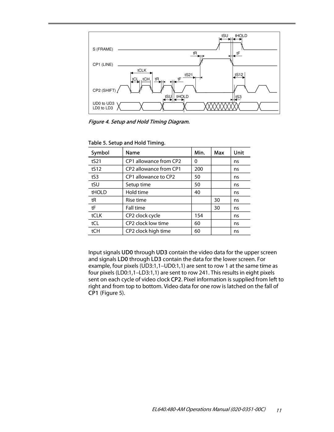
Figure 4. Setup and Hold Timing Diagram.
Table 5. Setup and Hold Timing.
Symbol | Name | Min. | Max | Unit |
|
|
|
|
|
tS21 | CP1 allowance from CP2 | 0 |
| ns |
tS12 | CP2 allowance from CP1 | 200 |
| ns |
tS3 | CP1 allowance to CP2 | 50 |
| ns |
tSU | Setup time | 50 |
| ns |
tHOLD | Hold time | 40 |
| ns |
tR | Rise time |
| 30 | ns |
tF | Fall time |
| 30 | ns |
|
|
|
|
|
tCLK | CP2 clock cycle | 154 |
| ns |
|
|
|
|
|
tCL | CP2 clock low time | 60 |
| ns |
|
|
|
|
|
tCH | CP2 clock high time | 60 |
| ns |
|
|
|
|
|
Input signals UD0 through UD3 contain the video data for the upper screen and signals LD0 through LD3 contain the data for the lower screen. For example, four pixels
11 |