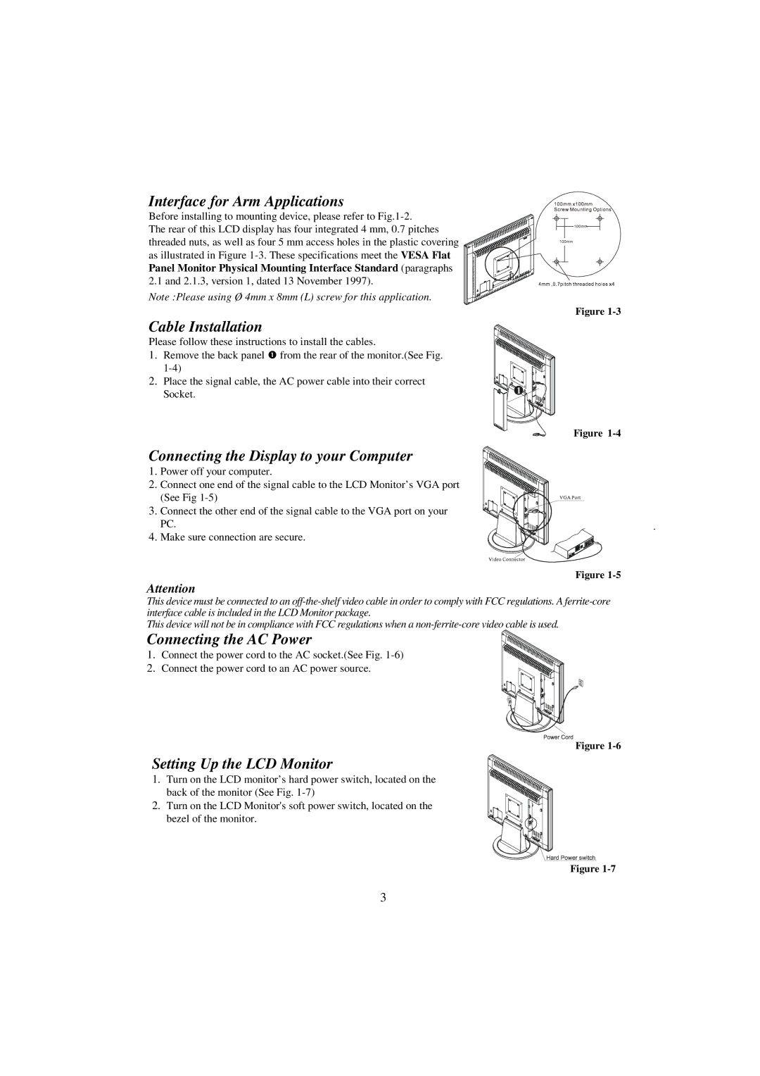
Interface for Arm Applications
Before installing to mounting device, please refer to
The rear of this LCD display has four integrated 4 mm, 0.7 pitches threaded nuts, as well as four 5 mm access holes in the plastic covering as illustrated in Figure
Note :Please using Ø 4mm x 8mm (L) screw for this application.
Cable Installation
Please follow these instructions to install the cables.
1.Remove the back panel n from the rear of the monitor.(See Fig.
2.Place the signal cable, the AC power cable into their correct Socket.
Figure
Figure
Connecting the Display to your Computer
1. Power off your computer.
2. Connect one end of the signal cable to the LCD Monitor’s VGA port (See Fig
3. Connect the other end of the signal cable to the VGA port on your PC.
4. Make sure connection are secure.
Figure
Attention
This device must be connected to an
This device will not be in compliance with FCC regulations when a
Connecting the AC Power
1. Connect the power cord to the AC socket.(See Fig.
2. Connect the power cord to an AC power source.
Figure
Setting Up the LCD Monitor
1. Turn on the LCD monitor’s hard power switch, located on the back of the monitor (See Fig.
2.Turn on the LCD Monitor's soft power switch, located on the
bezel of the monitor.
Figure
3