APPENDIX (cont.)
Connector Pin Assignment
1 | 5 |
6 | 10 |
11 | 15 |
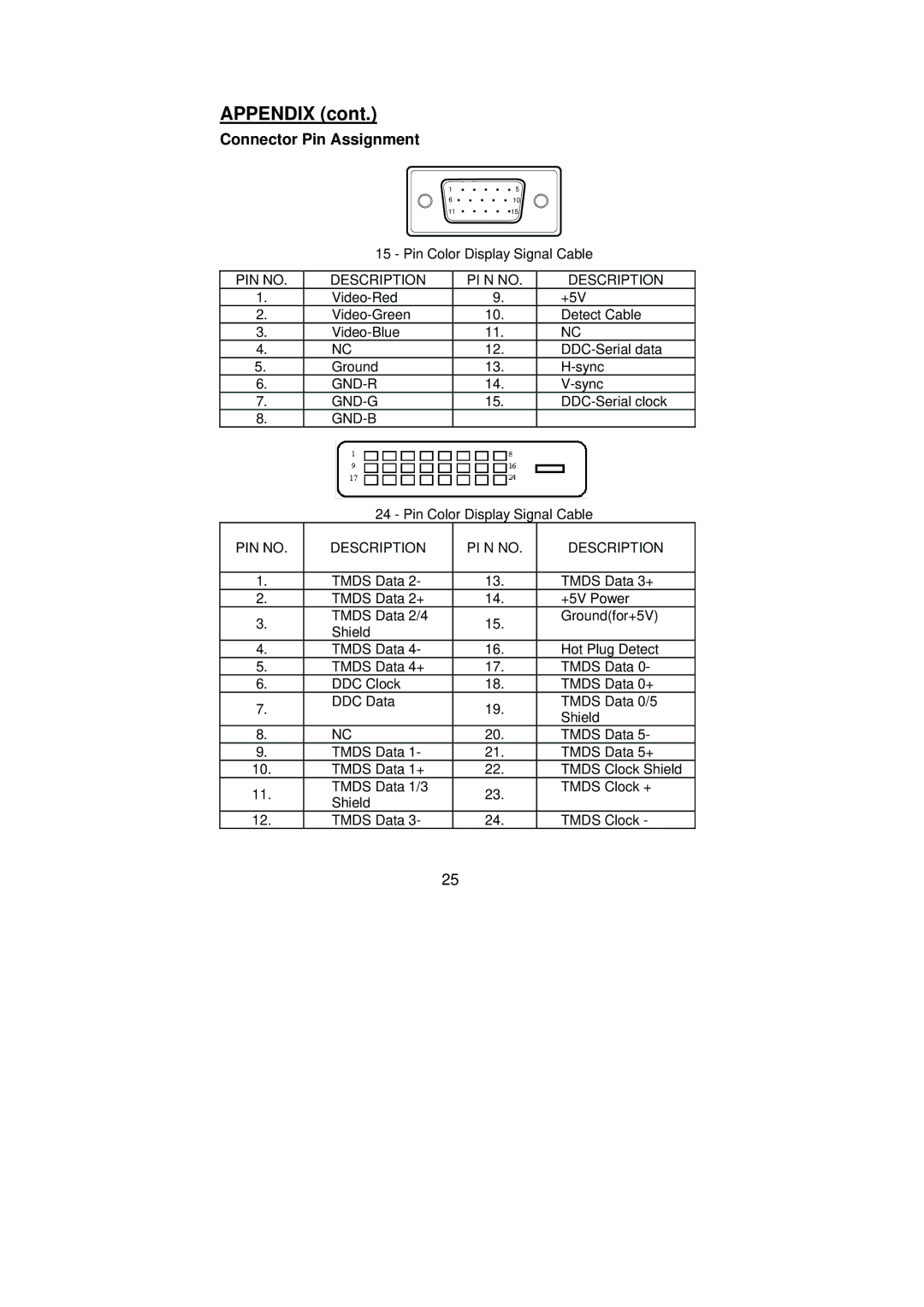
15 - Pin Color Display Signal Cable
PIN NO. | DESCRIPTION | PI N NO. | DESCRIPTION | ||
1. | 9. | +5V | |||
2. | 10. | Detect Cable | |||
3. | 11. | NC | |||
4. | NC | 12. | |||
5. | Ground | 13. | |||
6. | 14. | ||||
7. | 15. | ||||
8. |
|
|
| ||
|
|
|
|
|
|
|
|
|
|
|
|
24 - Pin Color Display Signal Cable
PIN NO. | DESCRIPTION | PI N NO. | DESCRIPTION |
|
|
|
|
1. | TMDS Data 2- | 13. | TMDS Data 3+ |
2. | TMDS Data 2+ | 14. | +5V Power |
3. | TMDS Data 2/4 | 15. | Ground(for+5V) |
Shield |
| ||
|
|
| |
4. | TMDS Data 4- | 16. | Hot Plug Detect |
5. | TMDS Data 4+ | 17. | TMDS Data 0- |
6. | DDC Clock | 18. | TMDS Data 0+ |
7. | DDC Data | 19. | TMDS Data 0/5 |
| Shield | ||
|
|
| |
8. | NC | 20. | TMDS Data 5- |
9. | TMDS Data 1- | 21. | TMDS Data 5+ |
10. | TMDS Data 1+ | 22. | TMDS Clock Shield |
11. | TMDS Data 1/3 | 23. | TMDS Clock + |
Shield |
| ||
|
|
| |
12. | TMDS Data 3- | 24. | TMDS Clock - |
25