TOOLS OF THE TRADE | | | | | | | | | | | | | | |
Listed next are the majority of the tools required to perform an installation.. | | | | | | |
Having the proper tools will make the installation that much easier.. | | | | | | | | |
• | Phillips head screwdriver | | | | | • Solderless, crimp-on connectors and a crimping tool |
• Electric drill and 3/16" and 1/8" drill bits | | • Safety glasses | | | | | | | | |
• | Permanent ink marker or pencil | | | | • DMM or VOM | | | | | | | | |
• | Safety glasses | | | | | • Nylon tie straps | | | | | | | | |
• | Wire strippers and cutters | | | | | • Wire crimper | | | | | | | | |
• | Electrical tape | | | | | • Grommets for passing wires through metal car walls |
• | Amplifier Power Wire | | | | | | | | | | | | | | | |
End Panel Layouts | | | | | | | | | | | | | | |
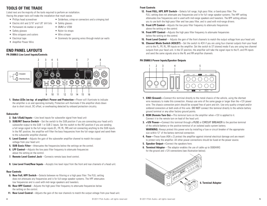
PA D5000.5 Line Level Inputs/Controls | | | | | | | | | | | | |
| 2 | | 3 | 4 | 5 | | | 6 | | | 7 | | 8 | |
| INPUT | SUB | INT | | | SUB | | | REMOTE LEVEL CONTROL | FL | INPUT | RL |
| | SUB | | | |
| | | | | | | | | | | | | |
| | | | LEVEL | SONIC | | LPF | | | | | | |
1 | | | SOURCE | | | | | | | | | | | | |
SUB 1 | | | 6V | 200mV | 20Hz | 38Hz | | 40Hz | 220Hz | | | | | | |
| | | | | | | | | |
| | | REAR | | | | FRONT | | | | | | | | |
| | | | | | HPF | | | | | | | | |
| | | FULL | HPF | | | BPF | | | | CHANNEL | | | |
| | | | | FULL | | | | | | |
| | | | | | | | | MODE | | | |
| | | | | | | | | | | | | | | |
| SUB 2 | | | 40Hz | 4000Hz 6V | 200mV | 80Hz 4000Hz 40Hz 400Hz | 6V | 200mV | | FR | | RR |
| | | HPF | LEVEL | LPF | HPF | LEVEL 4CH | ST | |
| | | | | | |
1.Status LEDs (on top of amplifier): Power and Protection—Power will illuminate to indicate the amplifier is on and operating normally; Protection will illuminate if the amplifier shuts down due to short circuit, DC offset, or overheating detected by onboard protection circuitry..
Subwoofer
2.Sub 1/Sub2 Inputs—Line level inputs for subwoofer signal from head unit
3.SUB/INT Source Switch—Set the switch to the SUB position if you are connecting your head unit’s subwoofer output to the SUB 1 or SUB 2 inputs. Set the switch to the INT position if you are sending
a full range signal to the full range inputs (FL, FR, RL, RR) and not connecting anything to the SUB inputs..
In the INT position, the amplifier will filter the bass frequencies from the full range signal and send them to the subwoofer amplifier channel..
4.Level Control—Adjusts the gain of the subwoofer amplifier channel to match the output voltage from your head unit..
5.SUB Sonic Filter—Attenuates the frequencies below the settings on the control..
6.LPF Control—Adjusts the low pass filter frequency to attenuate frequencies above the setting on the control..
7.Remote Level Control Jack—Connects remote bass level control..
8.Line Level Front/Rear Inputs—Accepts line level input from the front and rear channels of a head unit..
Rear Controls
9.Rear Full, HPF Switch—Selects between no filtering or a high pass filter.. The FULL setting does not attenuate any frequencies and is for full-range speaker systems.. The HPF attenuates low frequencies and is used with mid-range speakers and tweeters..
10.Rear HPF Control—Adjusts the high pass filter frequency to attenuate frequencies below the setting on the control..
11.Rear Level Control—Adjusts the gain of the rear channels to match the output voltage from your head unit..
Front Controls
12.Front FULL, HPF, BPF Switch—Selects full range, high pass filter, or band-pass filter.. The
FULL setting does not attenuate any frequencies and is for full range speaker systems.. The HPF setting attenuates low frequencies and is used with mid-range speakers and tweeters.. The BPF setting allows you to use both the high pass filter and low pass filter, and is used with mid-range drivers..
13.Front LPF Control—Adjusts the low pass filter frequency to attenuate frequencies above the setting on the control..
14.Front HPF Control—Adjusts the high pass filter frequency to attenuate frequencies below the setting on the control..
15.Front Level Control— Adjusts the gain of the front channels to match the output voltage from your head unit..
16.Channel Mode Switch (4CH/ST)—Set the switch to 4CH if you are using four channel outputs from your head unit to the FL, FR, RL, RR inputs on the amplifier.. Set the switch to ST (stereo) mode if you are using two channel outputs from your head unit.. In the ST position, the amplifier will take the signal input to the FL and FR inputs and send the same signals also to the RL and RR amplifier channels.
PA D5000.5 Power Inputs/Speaker Outputs | | | | | |
1 | 2 | 3 | 4 | | | 5 | | |
| | | | SUB | RL | RR | FL | FR |
GND | REM | 12V | | | | | | |
| | 40A | 40A | SUB | RL | RR | FL | FR |
1.GND (Ground)—Connect this terminal directly to the metal chassis of the vehicle, using the shortest wire necessary to make this connection. Always use wire of the same gauge or larger than the +12V power wire.. The chassis connection point should be scraped free of paint and dirt.. Use only quality crimped and/or soldered connectors at both ends of this wire.. DO NOT connect this terminal directly to the vehicle battery ground terminal or any other factory ground points..
2.REM (Remote Turn On)—This terminal turns on the amplifier when +12V is applied to it.
Connect it to the remote turn on lead of the head unit..
3.+12V Power—Connect this terminal through a FUSE or CIRCUIT BREAKER to the positive terminal of the vehicle battery or the positive terminal of an isolated audio system battery..
WARNING: Always protect this power wire by installing a fuse or circuit breaker of the appropriate size within 12" of the battery terminal connection.
4.Fuse—These fuses (40A x 2) protect the amplifier against internal electrical damage and are meant to protect only the amplifier.. All other power connections should be fused at the power source..
5.Speaker Output—Connect the speakers here..
6.Terminal Adaptor—The adaptor enables the use of cable up to 0000AWG for the ground and +12V connections (see illustration below).
6. Terminal Adaptor