FULL RANGE MM651UM & MM6501UM
ENGLISH
Figure 1 |
|
|
|
|
|
MM651UM BASIC COAXIAL CONNECTION |
|
|
|
|
|
Figure 1 |
|
|
|
|
|
CONNEXION D’UN HAUT- |
|
|
|
|
|
PARLEUR COAXIAL |
|
|
|
|
|
Figura 1 |
|
|
|
|
|
CONEXIÓN COAXIAL BÁSICA | Amplifier |
| |||
Abbildung 1 |
|
|
|
|
|
EINFACHE KOAXIALVERBINDUNG |
|
|
|
|
|
Figura 1 |
|
|
|
|
|
CONNESSIONE COASSIALE DI BASE |
|
|
|
|
|
Figura 1 |
|
|
|
|
|
|
|
|
|
| |
CONEXÃO COAXIAL BÁSICA |
|
|
|
|
|
Tweeter
Mid-Woofer
+–
Coaxial speaker
Figure 2
BASIC COMPONENT CONNECTION INSTALLING MM6501UM
Figure 2
CONNEXION DES COMPOSANTS INSTALLATION: MM6501UM
MM6501UM
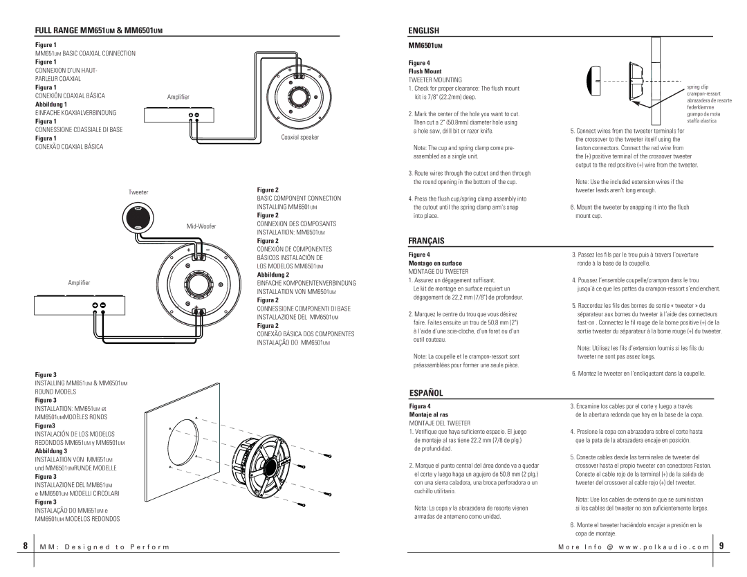
Figure 4
Flush Mount
TWEETER MOUNTING
1.Check for proper clearance: The flush mount kit is 7/8" (22.2mm) deep.
2.Mark the center of the hole you want to cut. Then cut a 2" (50.8mm) diameter hole using a hole saw, drill bit or razor knife.
Note: The cup and spring clamp come pre- assembled as a single unit.
3.Route wires through the cutout and then through the round opening in the bottom of the cup.
4.Press the flush cup/spring clamp assembly into the cutout until the spring clamp arm's snap into place.
spring clip
5.Connect wires from the tweeter terminals for the crossover to the tweeter itself using the faston connectors. Connect the red wire from the (+) positive terminal of the crossover tweeter output to the red positive (+) wire from the tweeter.
Note: Use the included extension wires if the tweeter leads aren't long enough.
6.Mount the tweeter by snapping it into the flush mount cup.
+ –
Figura 2
CONEXIÓN DE COMPONENTES
FRANÇAIS
Amplifier
– +
Figure 3
BÁSICOS INSTALACIÓN DE
LOS MODELOS MM6501UM
Abbildung 2
EINFACHE KOMPONENTENVERBINDUNG INSTALLATION VON MM6501UM
Figura 2
CONNESSIONE COMPONENTI DI BASE INSTALLAZIONE DEL MM6501UM
Figura 2
CONEXÃO BÁSICA DOS COMPONENTES INSTALAÇÃO DO MM6501UM
Figure 4
Montage en surface
MONTAGE DU TWEETER
1.Assurez un dégagement suffisant.
Le kit de montage en surface requiert un dégagement de 22,2 mm (7/8") de profondeur.
2.Marquez le centre du trou que vous désirez faire. Faites ensuite un trou de 50,8 mm (2") à l’aide d’une
Note: La coupelle et le
3.Passez les fils par le trou puis à travers l’ouverture ronde à la base de la coupelle.
4.Poussez l’ensemble coupelle/crampon dans le trou
jusqu’à ce que les pattes du
5.Raccordez les fils des bornes de sortie « tweeter » du séparateur aux bornes du tweeter à l’aide des connecteurs
Note: Utilisez les fils d’extension fournis si les fils du tweeter ne sont pas assez longs.
6.Montez le tweeter en l’encliquetant dans la coupelle.
INSTALLING MM651UM & MM6501UM ROUND MODELS
Figure 3
ESPAÑOL
INSTALLATION: MM651UM et MM6501UMMODÈLES RONDS
Figura3
INSTALACIÓN DE LOS MODELOS REDONDOS MM651UM y MM6501UM
Abbildung 3
INSTALLATION VON MM651UM und MM6501UMRUNDE MODELLE
Figura 3
INSTALLAZIONE DEL MM651UM
e MM6501UM MODELLI CIRCOLARI
Figura 3
INSTALAÇÃO DO MM651UM e
MM6501UM MODELOS REDONDOS
Figura 4
Montaje al ras
MONTAJE DEL TWEETER
1.Verifique que haya suficiente espacio. El juego de montaje al ras tiene 22.2 mm (7/8 de plg.) de profundidad.
2.Marque el punto central del área donde va a quedar el corte y luego haga un agujero de 50.8 mm (2 plg.) con una sierra caladora, una broca perforadora o un cuchillo utilitario.
Nota: La copa y la abrazadera de resorte vienen armadas de antemano como unidad.
3.Encamine los cables por el corte y luego a través
de la abertura redonda que hay en la base de la copa.
4.Presione la copa con abrazadera sobre el corte hasta que la pata de la abrazadera encaje en posición.
5.Conecte cables desde las terminales de tweeter del crossover hasta el propio tweeter con conectores Faston. Conecte el cable rojo de la terminal (+) de la salida de tweeter del crossover al cable rojo (+) del tweeter.
Nota: Use los cables de extensión que se suministran si los cables del tweeter no son suficientemente largos.
6.Monte el tweeter haciéndolo encajar a presión en la copa de montaje.
8
MM: Desi gned to P erf orm
M o r e I n fo @ w ww. p ol k au d i o. co m 9