Introduction
The KIRK ISDN Interface Card creates the interface between the switch and the digital cordless lines in the DECT solution. Furthermore, the KIRK ISDN Interface Card secures a galvanic isolation between the DECT solution and the switch (or the network provider).
1. KIRK ISDN NET5 Interface Card Features
The KIRK ISDN NET5 Interface Card contains the following features:
•The 2 Mbps KIRK ISDN Interface Card performs a 32 channel digital interface
•Up to 30 simultaneous conversations
•One RJ45 for 2 Mbit connection to Ethernet
•External data/paging and setup via RS232 serial interface
•Local RS232 for configuration, maintenance and debugging
•Transparency for the ISDN CLIP function
•Display (call info)
Additional KIRK ISDN QSIG 3.0 Interface Card features are:
•Call Hold
•Call Waiting
•Call Transfer
3.Installation
1Power down the KIRK Wireless Server.
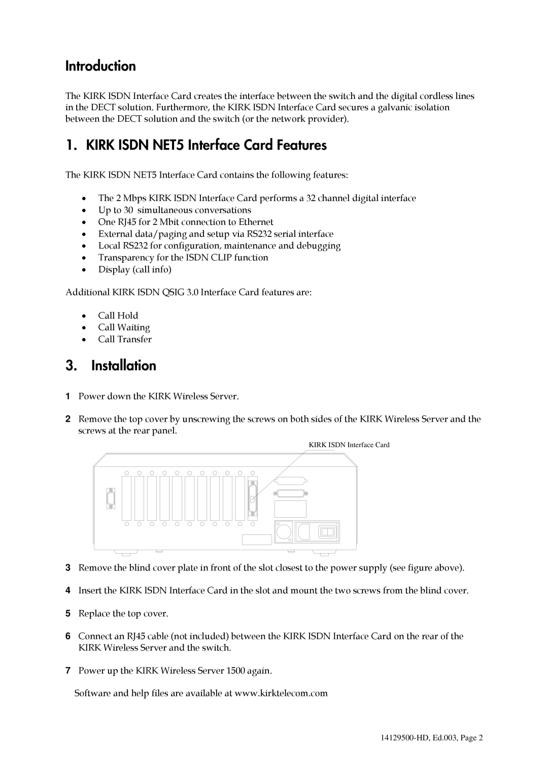
2Remove the top cover by unscrewing the screws on both sides of the KIRK Wireless Server and the screws at the rear panel.
KIRK ISDN Interface Card
3Remove the blind cover plate in front of the slot closest to the power supply (see figure above).
4Insert the KIRK ISDN Interface Card in the slot and mount the two screws from the blind cover.
5Replace the top cover.
6Connect an RJ45 cable (not included) between the KIRK ISDN Interface Card on the rear of the KIRK Wireless Server and the switch.
7Power up the KIRK Wireless Server 1500 again.
Software and help files are available at www.kirktelecom.com