ASSEMBLY
NOTE: This tool is shipped assembled with the exception of the auxiliary handle. Assembly time is approximately five minutes and no tools are required.
TO INSTALL AUXILIARY HANDLE
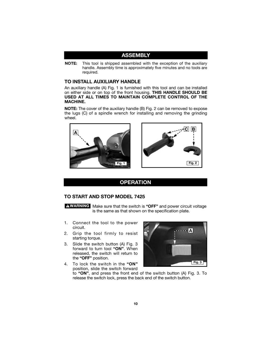
An auxiliary handle (A) Fig. 1 is furnished with this tool and can be installed on either side or on top of the front housing. THIS HANDLE SHOULD BE
USED AT ALL TIMES TO MAINTAIN COMPLETE CONTROL OF THE MACHINE.
NOTE: The cover of the auxiliary handle (B) Fig. 2 can be removed to expose the lugs (C) of a spindle wrench for installing and removing the grinding wheel.
A
![]() C
C ![]()
![]() B
B
Fig. 1
Fig. 2
OPERATION
TO START AND STOP MODEL 7425
![]() Make sure that the switch is “OFF” and power circuit voltage is the same as that shown on the specification plate.
Make sure that the switch is “OFF” and power circuit voltage is the same as that shown on the specification plate.
1. | Connect the tool to the power |
|
|
|
|
|
|
|
|
|
| circuit. |
|
|
|
|
|
|
|
|
|
|
|
|
|
|
| A |
|
| ||
2. | Grip the tool firmly to resist |
|
|
|
|
|
| |||
|
|
|
|
|
|
| ||||
|
|
|
|
|
|
|
|
| ||
| starting torque. |
|
|
|
|
|
|
|
|
|
3. | Slide the switch button (A) Fig. 3 |
|
|
|
|
|
|
|
|
|
| forward to turn tool “ON”. When |
|
|
|
|
|
|
|
|
|
| released, the switch will return to |
|
|
|
|
|
|
|
|
|
| the “OFF” position. |
|
|
|
|
|
|
|
|
|
4. | To lock the switch in the “ON” |
|
|
|
|
|
|
| Fig. 3 |
|
|
|
|
|
|
|
|
|
| ||
position, slide the switch forward
to “ON”, and press the front end of the switch button (A) Fig. 3. To release the switch lock, press the back end of the switch button.
10
